Maintenance
4-12
TDS3000C Series S ervice Manual
8. While pressing in on the hub assembly with your fingers, rotate the handle to
its full upright position. The hub assembly should rotate with the handle.
9. Use the
1
@
8
inch flat-bladed screwdriver to push the metal pin in to lock the
hub assembly.
NOTE. Do not push the metal pin completely into the hub assembly. Leave it out
approximately 1.5 mm (
1
/
16
inch).
10. Verify that neither hub assembly rotates when you rotate the handle.
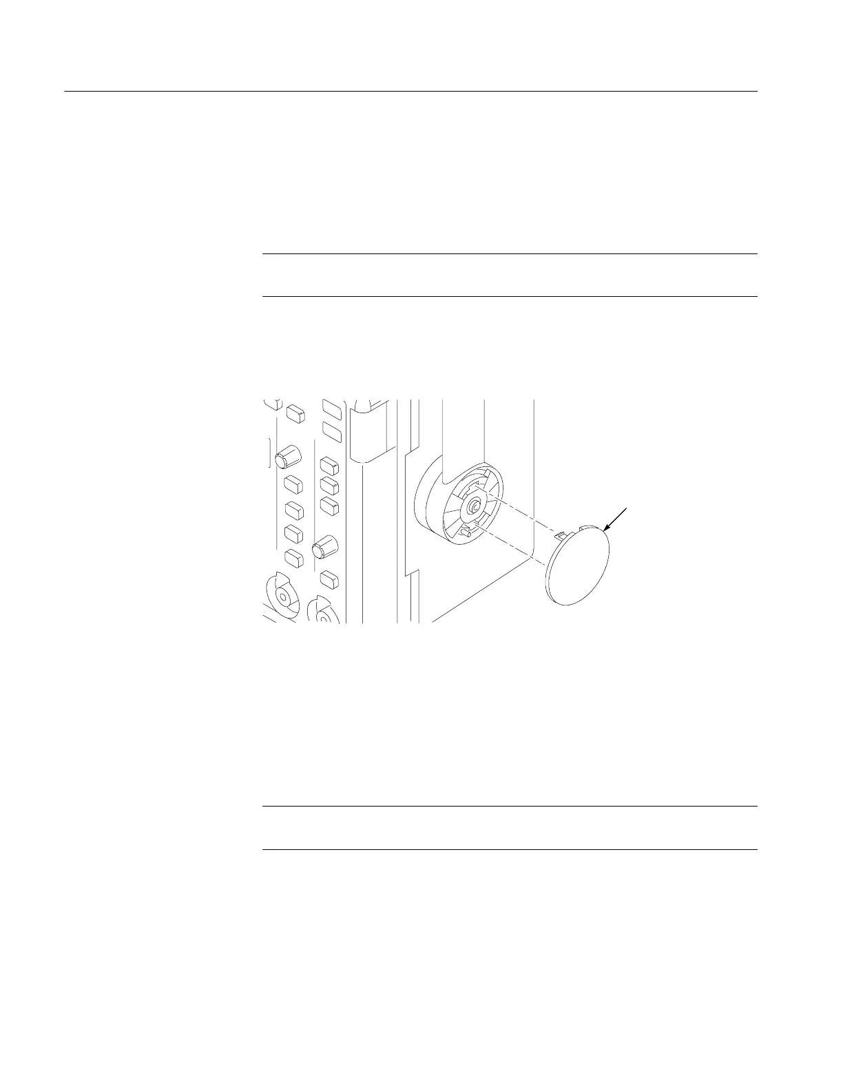
11. Snap the hub covers into place over the hub assemblies. See Figure 4 --3.
Hub cover
Figure 4- 3: Reinstalling a hub cover
You will need a TORX T-15 screwdriver to remove the rear case.
Removal. Use this procedure to remove the rear case, feet, communication
module cover, and communication module guide.
NOTE. You must remove the handle assembly before you can remove the rear
case. Follow the procedure on page 4--8 to remove the handle.
1. Place the oscilloscope face down on soft surface (such as an anti-static mat),
with the bottom facing you.
2. Remove the T-15 TORX screw just above the power plug.
3. Remove the communication module cover or any communication module
that may be installed.
Rear Case
 Loading...