Maintenance
4-24
TDS3000C Series S ervice Manual
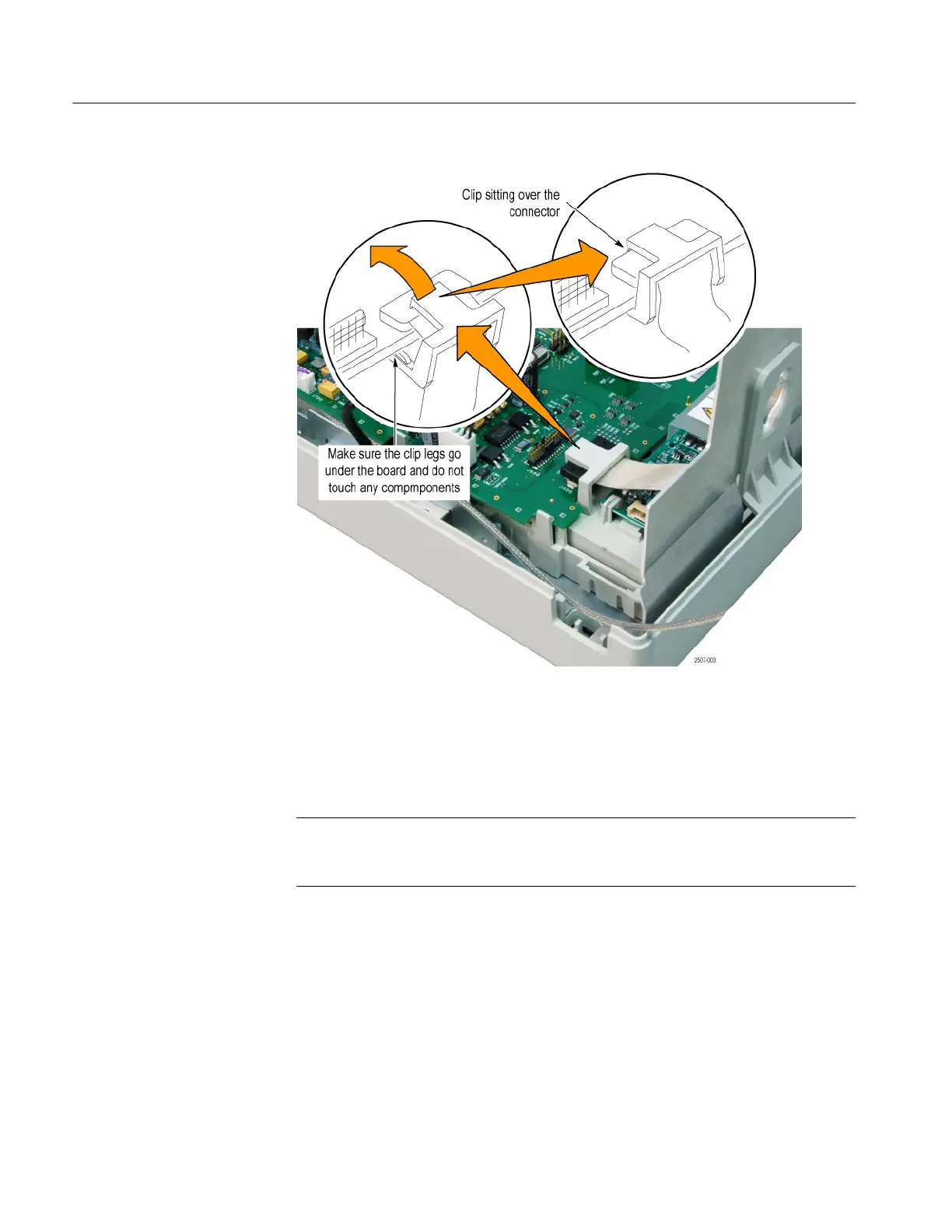
Figure 4- 10: Install the J500 connector clip
6. Use a magnetic long-bit TORX T-15 screwdriver to install the four screws
that secure the main board to the front-panel assembly.
NOTE. If after assembling the oscilloscope the display shows streaks, bars,
garbled data, or no image, open the instrument case and make sure that the
display cable is firmly and completely seated into connector J500.
7. Connect the front-panel cable to the main board at J700.
8. Connect the front-panel USB cable to the main board at J805.
9. Use Kapton tape to secure the display cable as shown in Figure 4--11. Cut
the tape around the inverter power connector.
10. On four-channel models, use Kapton tape to secure the trigger cable to the
side of the chassis. Arrange the cable for the most clearance between the
trigger cable and the display cable.
 Loading...