Maintenance
4-28
TDS3000C Series S ervice Manual
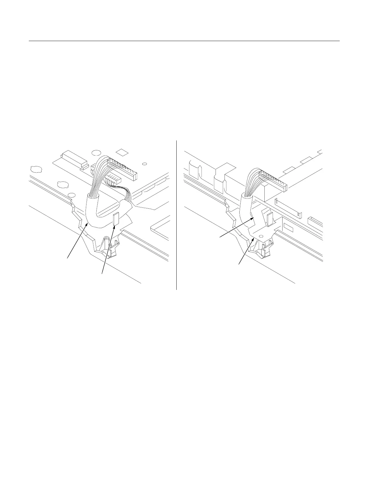
5. Route the front-panel cable so that it lies parallel to and along the top edge of
the bezel button flex circuit. Position the black vinyl cable cover so that the
wires are exposed from the front panel connector to just over the edge of the
front panel board.
6. Route the front panel cable through the cable post on the front panel and tuck
part of the cable just under the bottom corner of the front panel board. See
Figure 4--14.
Notch
Front-panel cable
Front chassis
Cable post
Figure 4- 14: Front-panel cable routing
7. Insert the front chassis assembly into the oscilloscope. Insert the right end of
the front chassis slightly ahead of the left end to clear a slight interference at
the right end of the chassis.
8. Route the front-panel cable through the notch located on the bottom edge of
the front chassis. See Figure 4--14.
9. Use the TORX T-10 screwdriver to insert the two screws that secure the front
chassis to the front case.
 Loading...