Maintenance
TDS3000C Series S ervice Manual
4-13
4. Lift the rear cover off of the oscilloscope chassis.
5. Remove both feet if necessary to replace them, otherwise leave the feet
installed in the back cabinet.
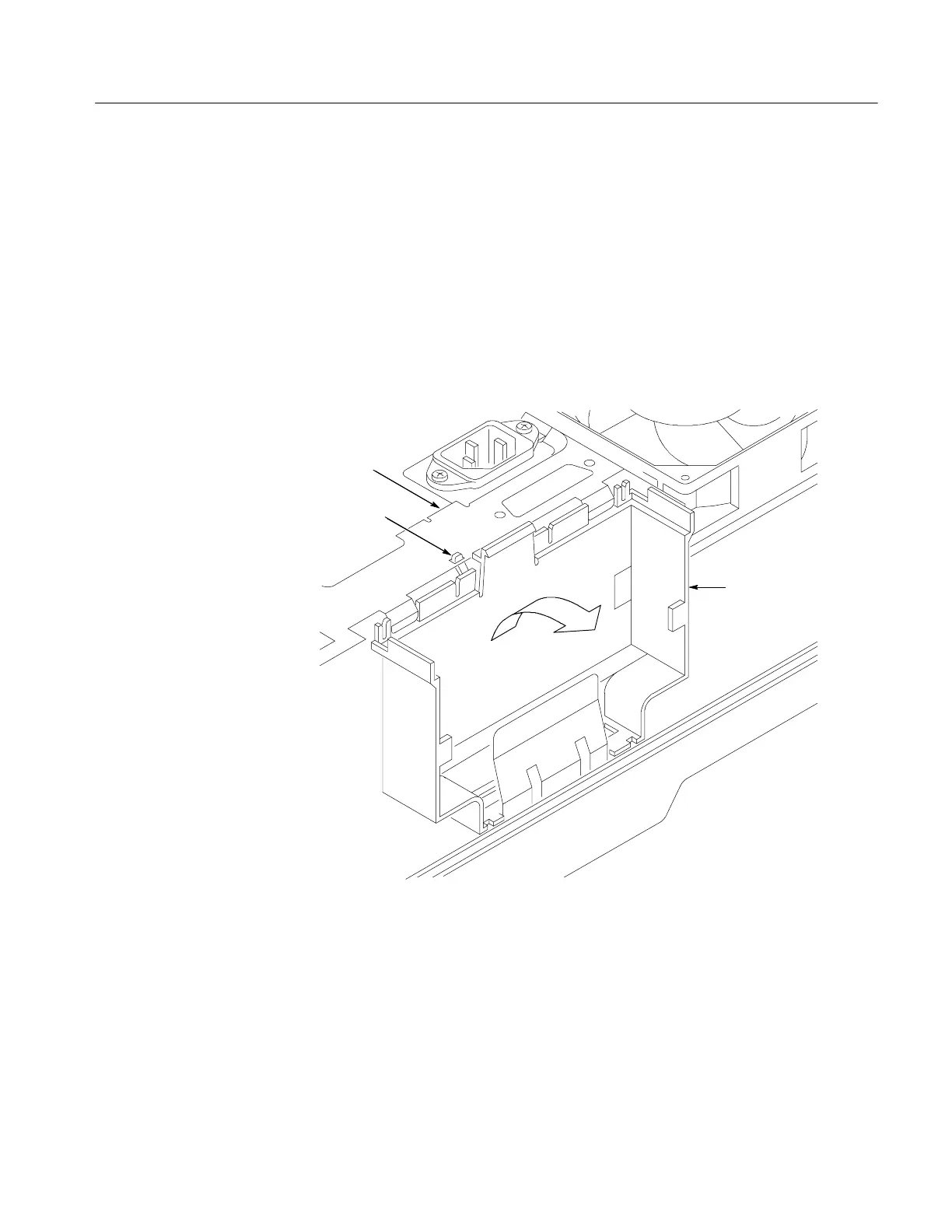
6. To remove the communication module guide, gently lift the chassis to
release the small communication module guide tab, move the module guide
slightly away from the chassis, and then lift the module guide away from the
oscilloscope. See Figure 4--4. Note that there are alignment pins along the
front edge of the module guide that insert into the main board when you
reinstall the module guide.
Tab
Communication
module guide
Chassis
Figure 4- 4: Communication module guide
Installation. Use this procedure to install the communication module guide, feet,
rear case, and communication module cover.
1. Place the oscilloscope face down on soft surface (such as an anti-static mat),
with the bottom facing you.
 Loading...