2.2.2 Controlling and Monitoring the Time-base Submodule
TBCTL[SYNCOSEL]
TBPRD
PeriodActive
TBPRD
PeriodShadow
16
TBCTL[SWFSYNC]
CTR=PRD
TBPHS
PhaseActiveReg
Counter
UP/DOWN
16
Sync
Out
Select
EPWMxSYNCO
Reset
Load
16
TBCTL[PHSEN]
CTR=Zero
CTR=CMPB
Disable
X
EPWMxSYNCI
TBCTL[PRDLD]
TBCTR[15:0]
Mode
TBCTL[CTRMODE]
CTR=Zero
CTR_max
TBCLK
Clock
Prescale
SYSCLKOUT
TBCLK
TBCTL[HSPCLKDIV]
TBCTL[CLKDIV]
CTR_dir
TBCTR
CounterActiveReg
clk
Max
Dir
Zero
Time-Base (TB) Submodule
Table 2-2 shows the registers used to control and monitor the time-base submodule.
Table 2-2. Time-Base Submodule Registers
Register Address offset Shadowed Description
TBCTL 0x0000 No Time-Base Control Register
TBSTS 0x0001 No Time-Base Status Register
TBPHSHR 0x0002 No HRPWM extension Phase Register
(1)
TBPHS 0x0003 No Time-Base Phase Register
TBCTR 0x0004 No Time-Base Counter Register
TBPRD 0x0005 Yes Time-Base Period Register
(1)
This register is available only on ePWM instances that include the high-resolution extension (HRPWM). On ePWM modules that
do not include the HRPWM, this location is reserved. This register is described in the TMS320x28xx, 28xxx High-Resolution
Pulse Width Modulator (HRPWM) Reference Guide (SPRU924). See the device specific data manual to determine which ePWM
instances include this feature.
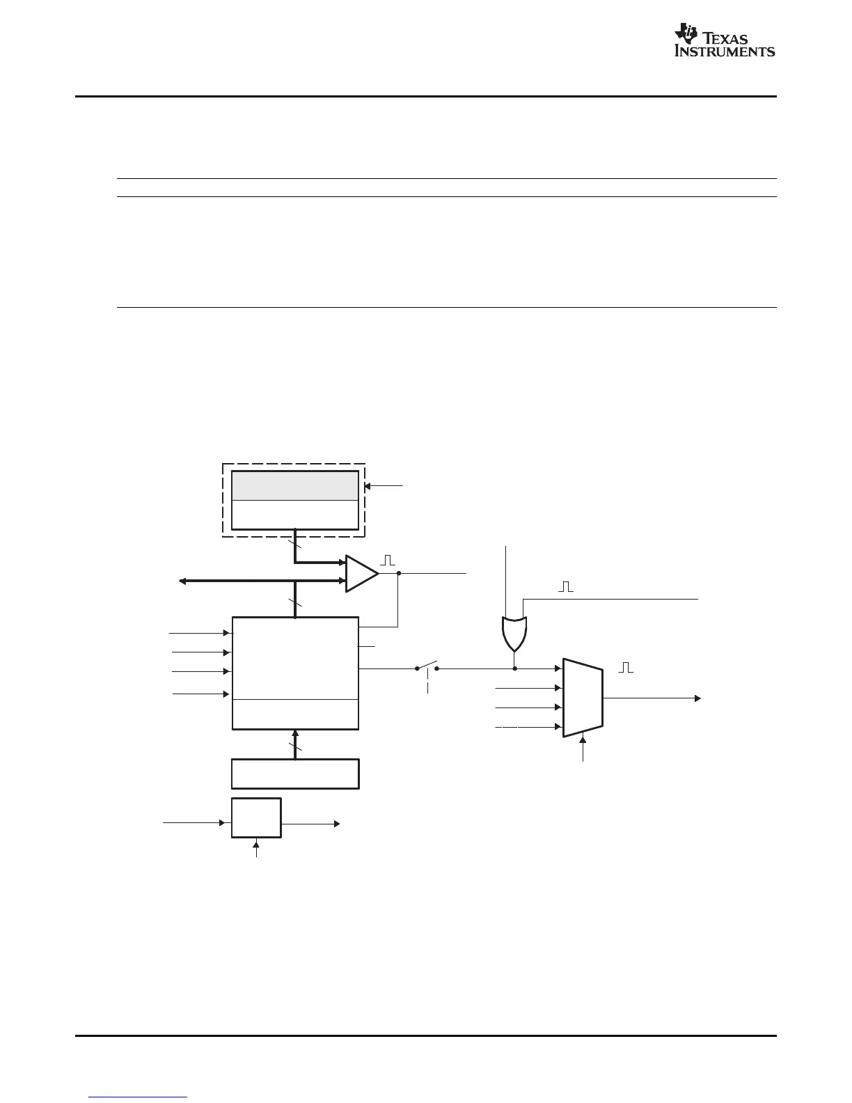
The block diagram in Figure 2-2 shows the critical signals and registers of the time-base submodule.
Table 2-3 provides descriptions of the key signals associated with the time-base submodule.
Figure 2-2. Time-Base Submodule Signals and Registers
ePWM Submodules24 SPRU791D – November 2004 – Revised October 2007
Submit Documentation Feedback
 Loading...