2.5 Dead-Band Generator (DB) Submodule
CTR = CMPB
CTR = CMPA
CTR_Dir
CTR = 0
CTR = PRD
Dead
Band
(DB)
Counter
Compare
(CC)
Action
Qualifier
(AQ)
EPWMxA
EPWMxB
CTR = CMPB
CTR = 0
EPWMxINT
EPWMxSOCA
EPWMxSOCB
EPWMxA
EPWMxB
TZ1
to TZ6
CTR = CMPA
Time-Base
(TB)
CTR = PRD
CTR = 0
CTR_Dir
EPWMxSYNCI
EPWMxSYNCO
EPWMxTZINT
PWM-
chopper
(PC)
Event
Trigger
and
Interrupt
(ET)
Trip
Zone
(TZ)
GPIO
MUX
ADC
PIE
PIE
2.5.1 Purpose of the Dead-Band Submodule
2.5.2 Controlling and Monitoring the Dead-Band Submodule
Dead-Band Generator (DB) Submodule
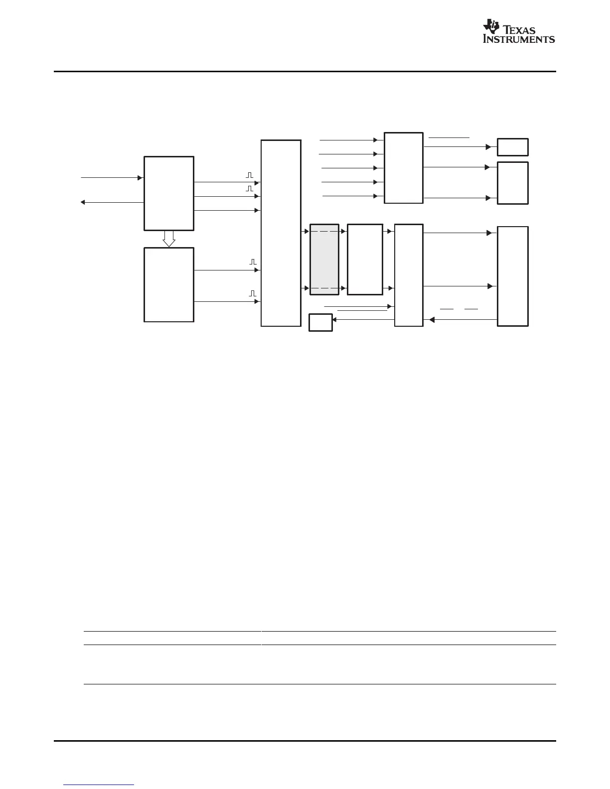
Figure 2-27 illustrates the dead-band submodule within the ePWM module.
Figure 2-27. Dead_Band Submodule
The "Action-qualifier (AQ) Module" section discussed how it is possible to generate the required
dead-band by having full control over edge placement using both the CMPA and CMPB resources of the
ePWM module. However, if the more classical edge delay-based dead-band with polarity control is
required, then the dead-band submodule described here should be used.
The key functions of the dead-band module are:
• Generating appropriate signal pairs (EPWMxA and EPWMxB) with dead-band relationship from a
single EPWMxA input
• Programming signal pairs for:
– Active high (AH)
– Active low (AL)
– Active high complementary (AHC)
– Active low complementary (ALC)
• Adding programmable delay to rising edges (RED)
• Adding programmable delay to falling edges (FED)
• Can be totally bypassed from the signal path (note dotted lines in diagram)
The dead-band submodule operation is controlled and monitored via the following registers:
Table 2-12. Dead-Band Generator Submodule Registers
Register Name Address offset Shadowed Description
DBCTL 0x000F No Dead-Band Control Register
DBRED 0x0010 No Dead-Band Rising Edge Delay Count Register
DBFED 0x0011 No Dead-Band Falling Edge Delay Count Register
ePWM Submodules50 SPRU791D – November 2004 – Revised October 2007
Submit Documentation Feedback
 Loading...