PIE
Event Trigger
Module Logic
CTR=Zero
CTR=PRD
CTR=CMPA
EPWMxINTn
CTR=CMPB
CTR_dir
Direction
qualifier
CTRU=CMPA
ETSEL reg
EPWMxSOCA
/n
/n
/n
EPWMxSOCB
ADC
clear
count
count
clear
count
clear
CTRD=CMPA
CTRU=CMPB
CTRD=CMPB
ETPS reg
ETFLG reg
ETCLR reg
ETFRC reg
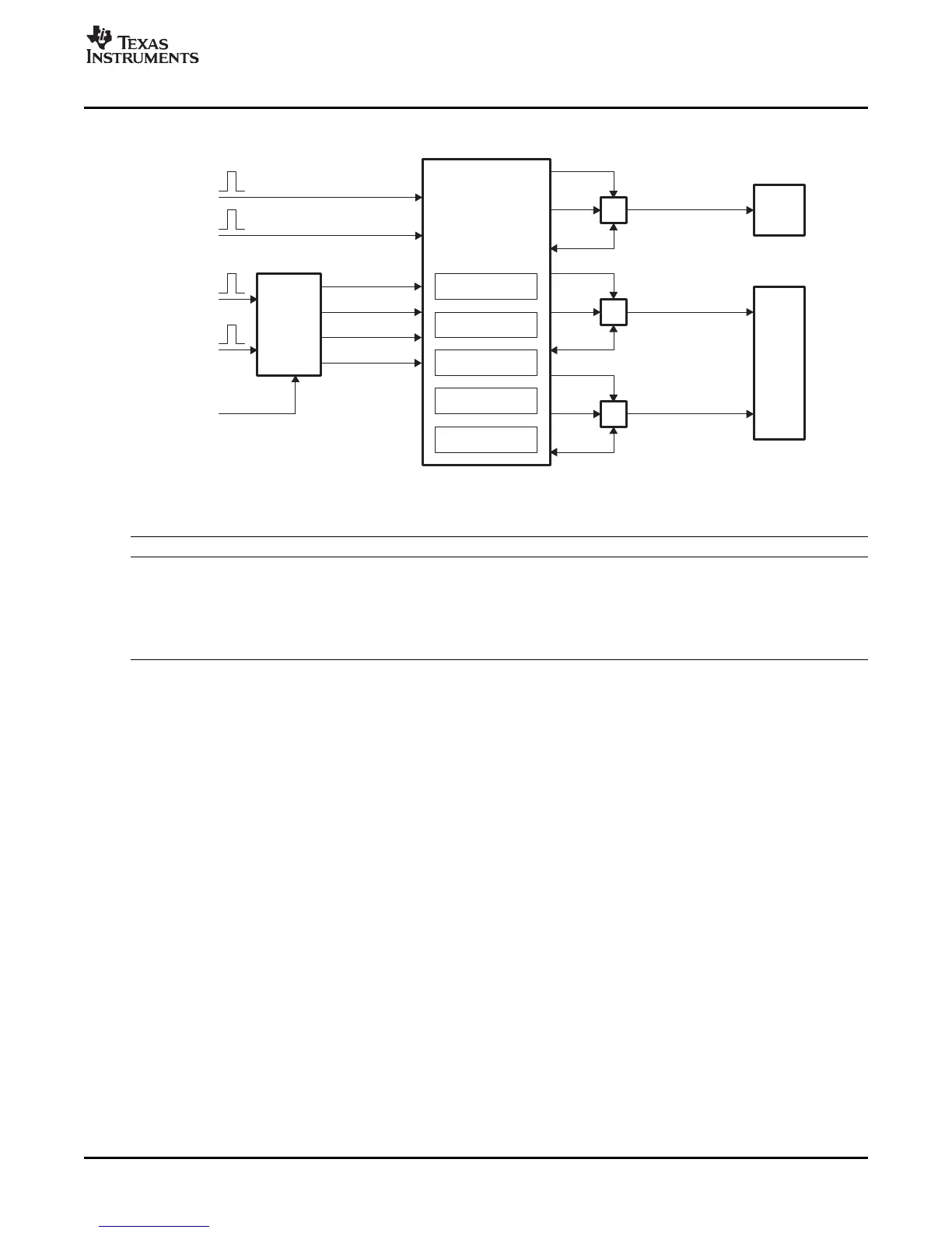
Event-Trigger (ET) Submodule
Figure 2-40. Event-Trigger Submodule Showing Event Inputs and Prescaled Outputs
The key registers used to configure the event-trigger submodule are shown in Table 2-19 :
Table 2-19. Event-Trigger Submodule Registers
Register Name Address offset Shadowed Description
ETSEL 0x0019 No Event-trigger Selection Register
ETPS 0x001A No Event-trigger Prescale Register
ETFLG 0x001B No Event-trigger Flag Register
ETCLR 0x001C No Event-trigger Clear Register
ETFRC 0x001D No Event-trigger Force Register
• ETSEL—This selects which of the possible events will trigger an interrupt or start an ADC conversion
• ETPS—This programs the event prescaling options mentioned above.
• ETFLG—These are flag bits indicating status of the selected and prescaled events.
• ETCLR—These bits allow you to clear the flag bits in the ETFLG register via software.
• ETFRC—These bits allow software forcing of an event. Useful for debugging or s/w intervention.
A more detailed look at how the various register bits interact with the Interrupt and ADC start of
conversion logic are shown in Figure 2-41 , Figure 2-42 , and Figure 2-43 .
Figure 2-41 shows the event-trigger's interrupt generation logic. The interrupt-period (ETPS[INTPRD]) bits
specify the number of events required to cause an interrupt pulse to be generated. The choices available
are:
• Do not generate an interrupt.
• Generate an interrupt on every event
• Generate an interrupt on every second event
• Generate an interrupt on every very third event
Which event can cause an interrupt is configured by the interrupt selection (ETSEL[INTSEL]) bits. The
event can be one of the following:
• Time-base counter equal to zero (TBCTR = 0x0000).
• Time-base counter equal to period (TBCTR = TBPRD).
• Time-base counter equal to the compare A register (CMPA) when the timer is incrementing.
• Time-base counter equal to the compare A register (CMPA) when the timer is decrementing.
• Time-base counter equal to the compare B register (CMPB) when the timer is incrementing.
• Time-base counter equal to the compare B register (CMPB) when the timer is decrementing.
SPRU791D – November 2004 – Revised October 2007 ePWM Submodules 65
Submit Documentation Feedback