3.1 Overview of Multiple Modules
CTR = 0
CTR=CMPB
X
EN
SyncOut
Phase reg
EPWMxA
EPWMxB
SyncIn
Φ=0°
3.2 Key Configuration Capabilities
Overview of Multiple Modules
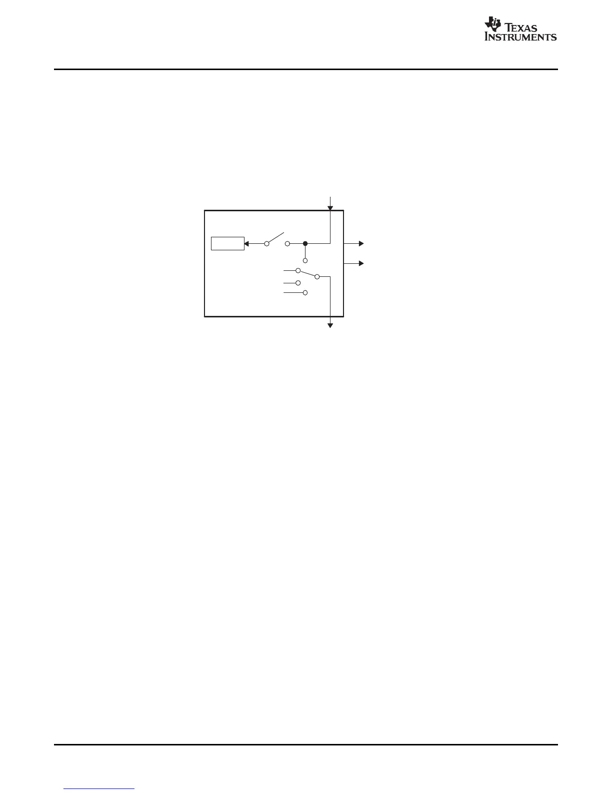
Previously in this user's guide, all discussions have described the operation of a single module. To
facilitate the understanding of multiple modules working together in a system, the ePWM module
described in reference is represented by the more simplified block diagram shown in Figure 3-1 . This
simplified ePWM block shows only the key resources needed to explain how a multiswitch power topology
is controlled with multiple ePWM modules working together.
Figure 3-1. Simplified ePWM Module
The key configuration choices available to each module are as follows:
• Options for SyncIn
– Load own counter with phase register on an incoming sync strobe—enable (EN) switch closed
– Do nothing or ignore incoming sync strobe—enable switch open
– Sync flow-through - SyncOut connected to SyncIn
– Master mode, provides a sync at PWM boundaries—SyncOut connected to CTR = PRD
– Master mode, provides a sync at any programmable point in time—SyncOut connected to CTR =
CMPB
– Module is in standalone mode and provides No sync to other modules—SyncOut connected to X
(disabled)
• Options for SyncOut
– Sync flow-through - SyncOut connected to SyncIn
– Master mode, provides a sync at PWM boundaries—SyncOut connected to CTR = PRD
– Master mode, provides a sync at any programmable point in time—SyncOut connected to CTR =
CMPB
– Module is in standalone mode and provides No sync to other modules—SyncOut connected to X
(disabled)
For each choice of SyncOut, a module may also choose to load its own counter with a new phase value
on a SyncIn strobe input or choose to ignore it, i.e., via the enable switch. Although various combinations
are possible, the two most common—master module and slave module modes—are shown in Figure 3-2 .
70 Applications to Power Topologies SPRU791D – November 2004 – Revised October 2007
Submit Documentation Feedback
 Loading...