2.5.3 Operational Highlights for the Dead-Band Submodule
0
1
S2
1
0
S1
RED
OutIn
Risingedge
delay
(10-bit
counter)
(10-bit
counter)
delay
Fallingedge
In Out
FED
1
0
S3
0
S0
1
EPWMxA
EPWMxB
DBCTL[POLSEL] DBCTL[OUT_MODE]
S5
DBCTL[IN_MODE]
1
0
S4
0
1
EPWMxA in
EPWMxBin
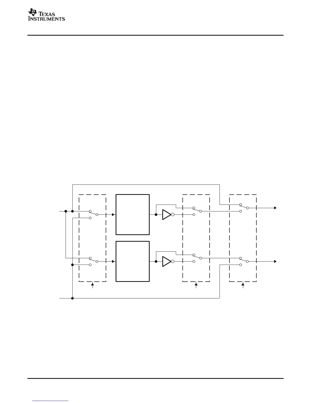
Dead-Band Generator (DB) Submodule
The following sections provide the operational highlights.
The dead-band submodule has two groups of independent selection options as shown in Figure 2-28 .
• Input Source Selection:
The input signals to the dead-band module are the EPWMxA and EPWMxB output signals from the
action-qualifier. In this section they will be referred to as EPWMxA In and EPWMxB In. Using the
DBCTL[IN_MODE) control bits, the signal source for each delay, falling-edge or rising-edge, can be
selected:
– EPWMxA In is the source for both falling-edge and rising-edge delay. This is the default mode.
– EPWMxA In is the source for falling-edge delay, EPWMxB In is the source for rising-edge delay.
– EPWMxA In is the source for rising edge delay, EPWMxB In is the source for falling-edge delay.
– EPWMxB In is the source for both falling-edge and rising-edge delay.
• Output Mode Control:
The output mode is configured by way of the DBCTL[OUT_MODE] bits. These bits determine if the
falling-edge delay, rising-edge delay, neither, or both are applied to the input signals.
• Polarity Control:
The polarity control (DBCTL[POLSEL]) allows you to specify whether the rising-edge delayed signal
and/or the falling-edge delayed signal is to be inverted before being sent out of the dead-band
submodule.
Figure 2-28. Configuration Options for the Dead-Band Submodule
Although all combinations are supported, not all are typical usage modes. Table 2-13 documents some
classical dead-band configurations. These modes assume that the DBCTL[IN_MODE] is configured such
that EPWMxA In is the source for both falling-edge and rising-edge delay. Enhanced, or non-traditional
modes can be achieved by changing the input signal source. The modes shown in Table 2-13 fall into the
following categories:
• Mode 1: Bypass both falling-edge delay (FED) and rising-edge delay (RED)
Allows you to fully disable the dead-band submodule from the PWM signal path.
• Mode 2-5: Classical Dead-Band Polarity Settings:
These represent typical polarity configurations that should address all the active high/low modes
required by available industry power switch gate drivers. The waveforms for these typical cases are
shown in Figure 2-29 . Note that to generate equivalent waveforms to Figure 2-29 , configure the
SPRU791D – November 2004 – Revised October 2007 ePWM Submodules 51
Submit Documentation Feedback
 Loading...