UP
DOWN
UP
DOWN
2
0
3
4
1
2
3
1
2
0
3
4
1
2
0
3
1
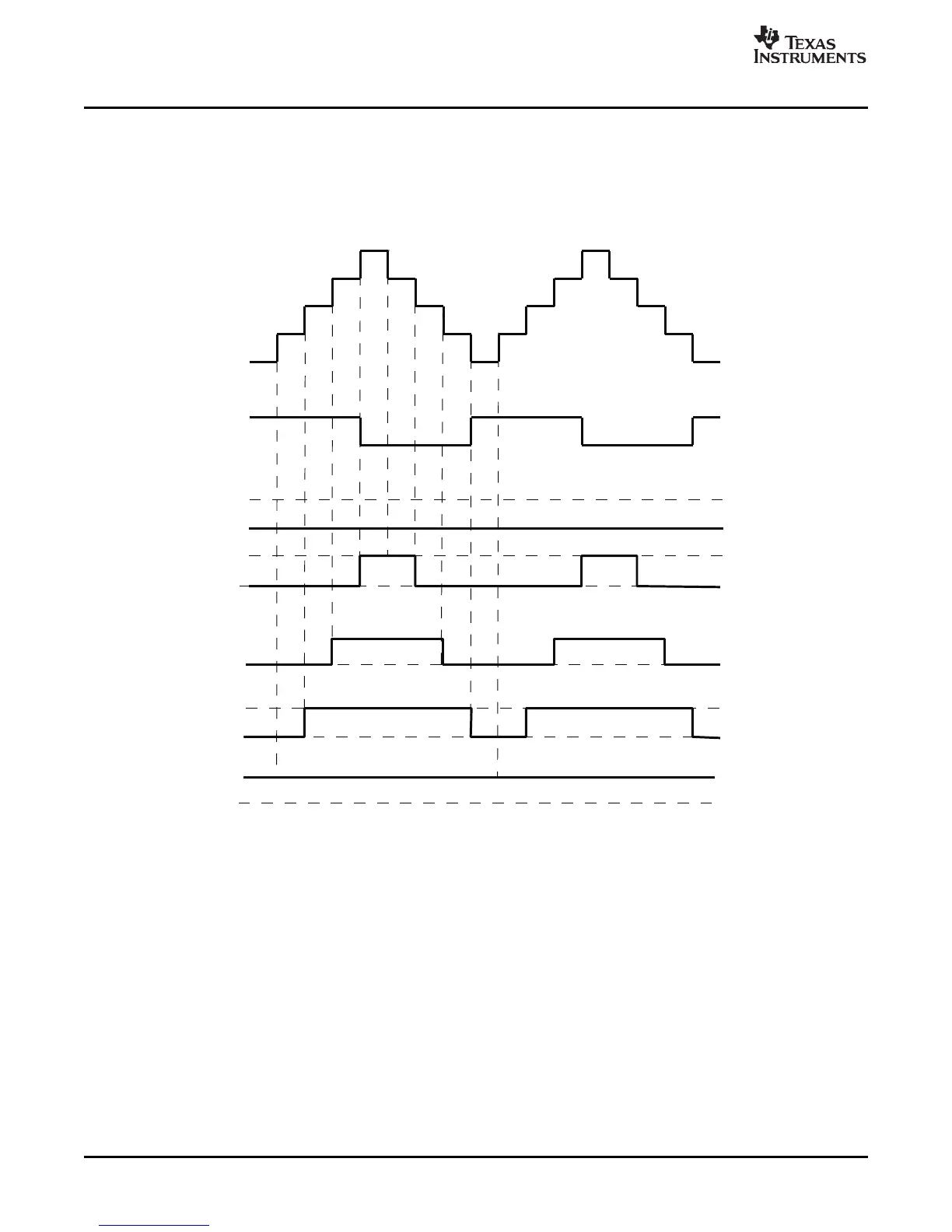
TBCNTR
TBCNTRDirection
EPWMxA/EPWMxB
Case2:
CMPA =3,25%Duty
Case3:
CMPA =2,50%Duty
Case3:
CMPA =1,75%Duty
Case4:
CMPA =0,100%Duty
Case1:
CMPA =4,0%Duty
EPWMxA/EPWMxB
EPWMxA/EPWMxB
EPWMxA/EPWMxB
EPWMxA/EPWMxB
Mode:Up-DownCount
TBPRD=4
CAU=SET,CAD=CLEAR
0%-100%Duty
Action-Qualifier (AQ) Submodule
When using this configuration in practice, if you load CMPA/CMPB on zero, then use CMPA/CMPB values
greater than or equal to 1. If you load CMPA/CMPB on period, then use CMPA/CMPB values less than or
equal to TBPRD-1. This means there will always be a pulse of at least one TBCLK cycle in a PWM period
which, when very short, tend to be ignored by the system.
Figure 2-20. Up-Down-Count Mode Symmetrical Waveform
The PWM waveforms in Figure 2-21 through Figure 2-26 show some common action-qualifier
configurations. The C-code samples in Example 2-2 through Example 2-7 shows how to configure an
ePWM module for each case. Some conventions used in the figures and examples are as follows:
• TBPRD, CMPA, and CMPB refer to the value written in their respective registers. The active register,
not the shadow register, is used by the hardware.
• CMPx, refers to either CMPA or CMPB.
• EPWMxA and EPWMxB refer to the output signals from ePWMx
• Up-Down means Count-up-and-down mode, Up means up-count mode and Dwn means down-count
mode
• Sym = Symmetric, Asym = Asymmetric
42 ePWM Submodules SPRU791D – November 2004 – Revised October 2007
Submit Documentation Feedback
 Loading...