J721E EVM Hardware Architecture
www.ti.com
74
SPRUIS4A–December 2019–Revised May 2020
Submit Documentation Feedback
Copyright © 2019–2020, Texas Instruments Incorporated
Jacinto7 J721E/DRA829/TDA4VM Evaluation Module (EVM)
Device Interface:
In this approach Common Processor PCB have a footprint PG-USON-8-1. Apple authentication device will
not be assembled to this footprint by default.
Required I2C0, Power, Reset and Ground signals from J721E SoC is routed to this footprint, as shown in
Table 43.
Table 43. APPLE AUTH Footprint U108 Pinout
Pin
No Signal Description
6 I2C0_SCL I2C slave interface, clock connection
2 I2C0_SDA I2C slave interface, data connection
7 APPLE_AUTH_RSTz Reset, Active low
8 VSYS_IO_3V3 Power 3.3 V
1, 9 DGND Ground
3,4,5 NC Not Connected
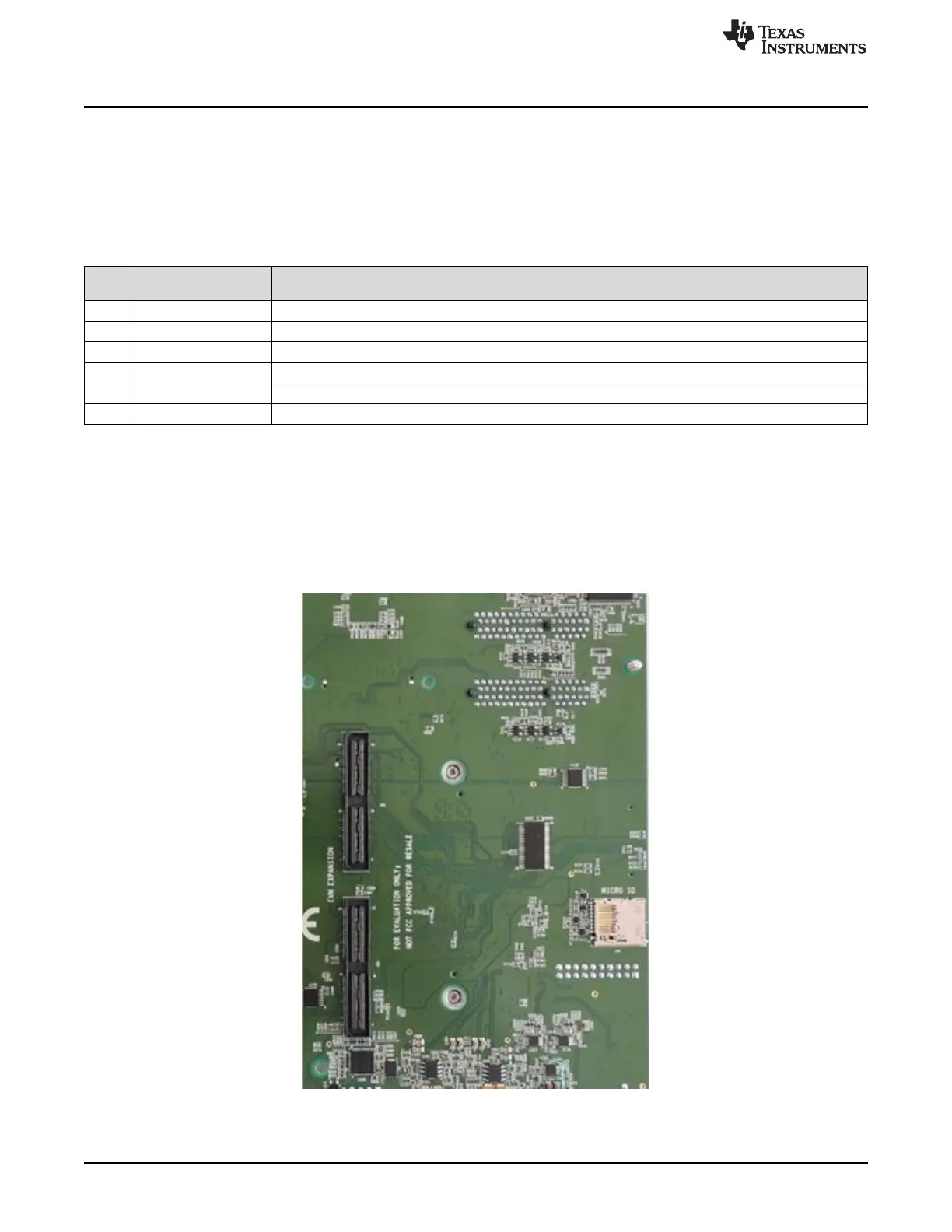
4.24 EVM Expansion Connectors
The Common processor board includes an Expansion connector of QSH-060-01-L-D-A-K with 5mm
mating height allowing multiple expansion boards (Infotainment or GESI Expansion) to be stacked below
the processor board.
Either Infotainment or GESI Expansion board can be plugged into EVM expansion connectors (J46 and
J51) at once.
Figure 58. Expansion Board Interface Connectors

 Loading...


