1
2
3
4
5
6
7
1
2
3
4
5
6
7
GP3
GP4
SENSE
VDD_EXTERNAL_3P3
VDD_EXTERNAL_3P3
VDDL_3P3
VDD_LDO
Jumper
Shunt
J19
1
2
3
4
5
6
7
1
2
3
4
5
6
7
VD_EXT_3P3
SDA_S
SCL_S
GP1
GP2
VSYNC_RST
VSS_IN
J17
www.ti.com
OPT3101EVM Hardware
7
SBAU309A–February 2018–Revised June 2018
Submit Documentation Feedback
Copyright © 2018, Texas Instruments Incorporated
OPT3101 Evaluation Module
3.3 Light-Emitting Diode (LED) and Photodiode (PD) for ToF Measurements
As the introduction states, this EVM is a single-pixel system. There is a single LED-photodiode pair that
connects to the OPT3101 and is used for ToF measurements. The EVM uses a 850-nm centroid (860-nm
peak) wavelength IR LED (SFH 4550), and a 900-nm peak sensitivity IR photodiode (SFH 213 FA).
Electroless nickel immersion gold (ENIG)cylinders on the EVM encircle both the LED and photodiode. The
cylinders provide both optical and electrical shielding between the LED and photodiode, this reduces
crosstalk.
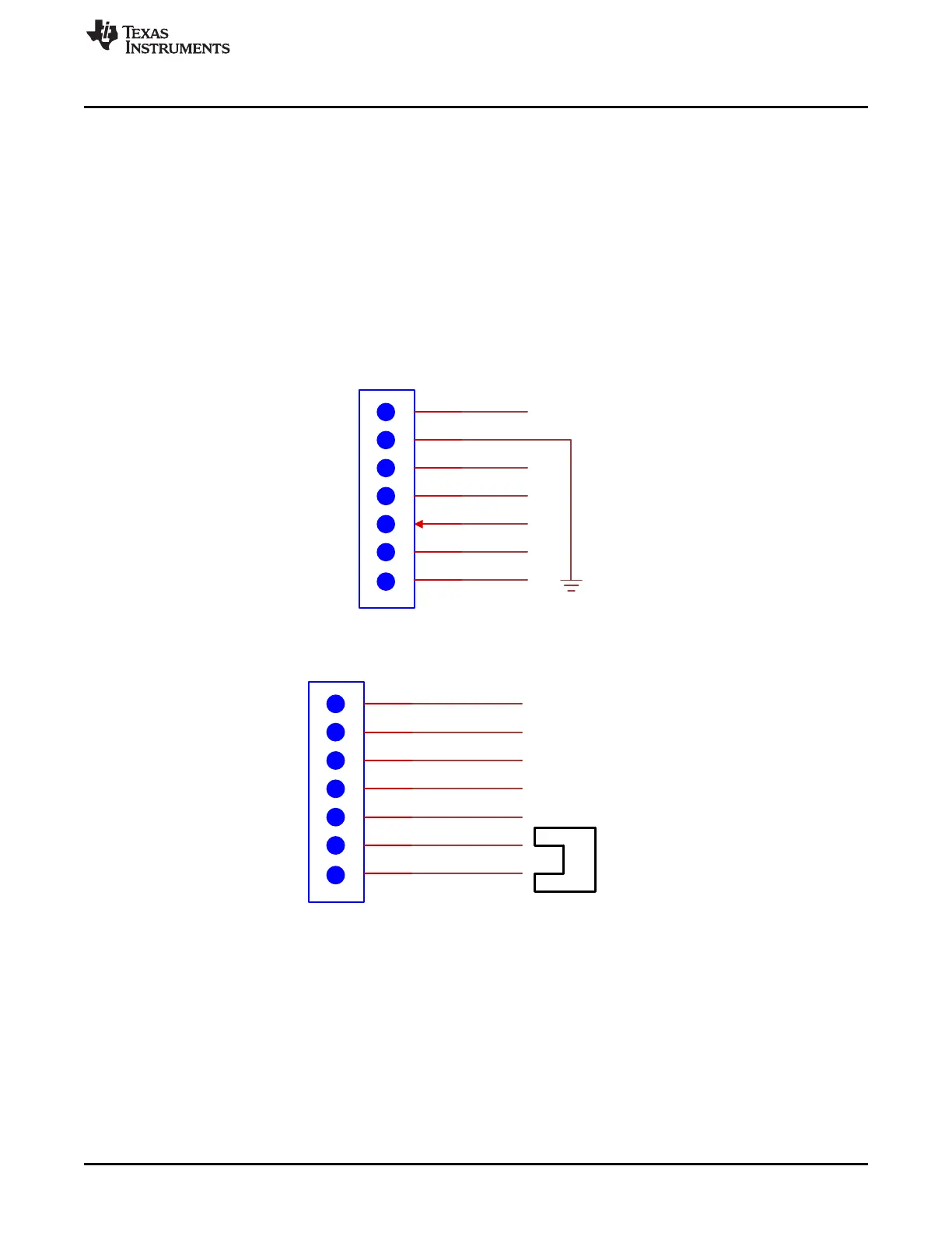
3.4 Headers and Power-On Jumper
The headers break out a number of signals from the EVM for debug and to provide more flexibility in the
ways the EVM can be used. Figure 6 shows how to power the board by placing the power-on jumper on
the bottom two pins of J19. This connects the 3.3-V output of the LDO to the rest of the components on
the EVM. Figure 5 and Figure 6 show the complete list of signals that are broken out to the headers.
Figure 5. J17 Header
Figure 6. J19 Header With Power-On Jumper Shown
 Loading...


