Driver
R
DRIVER
C
DRIVER
Z
DRIVER
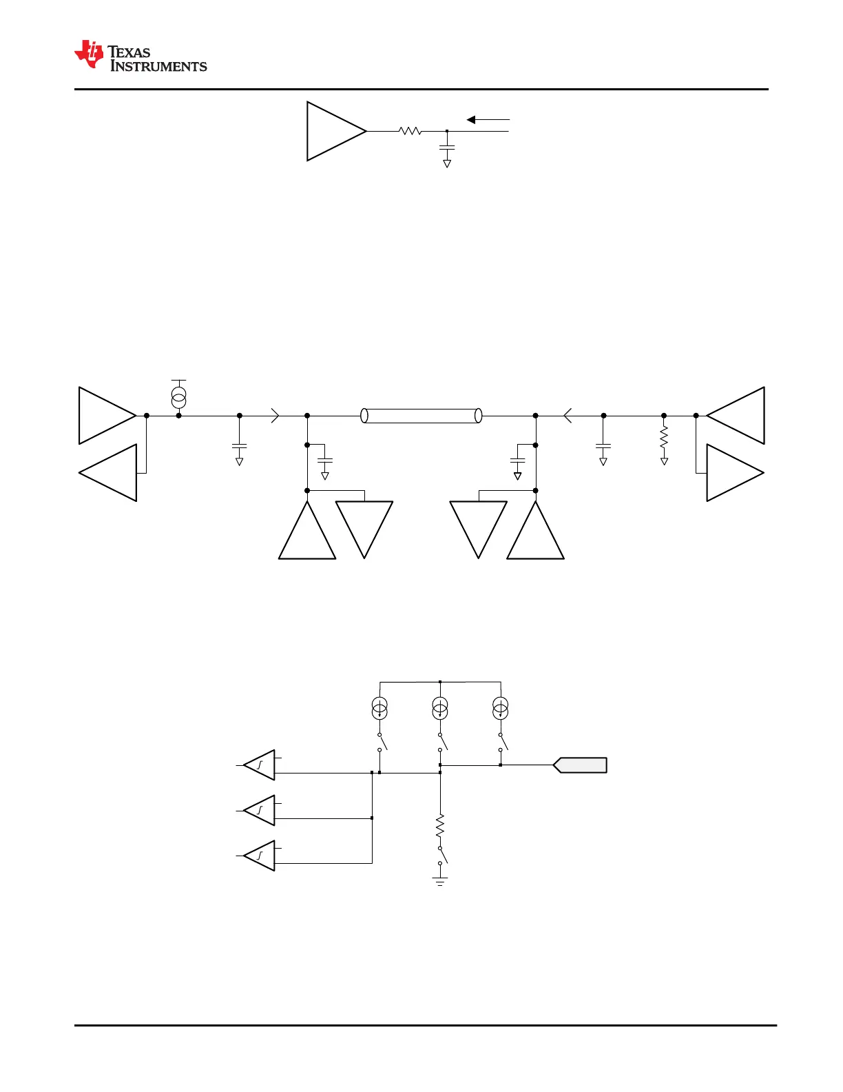
Figure 9-7. ZDRIVER Circuit
9.3.1.5 USB-PD BMC Receiver
The receiver block of the TPS65982 receives a signal that falls within the allowed Rx masks defined in the
USB PD specification. The receive thresholds and hysteresis come from this mask. The values for VRXTR and
VRXTF are listed in USB-PD Baseband Signal Requirements and Characteristics.
Figure 9-8 shows an example of a multi-drop USB-PD connection. This connection has the typical UFP (device)
to DFP (host) connection, but also includes cable USB-PD TX/Rx blocks. Only one system can be transmitting at
a time. All other systems are Hi-Z (ZBMCRX). The USB-PD Specification also specifies the capacitance that can
exist on the wire as well as a typical DC bias setting circuit for attach detection.
C
CBLPLUG
Tx
Rx
Tx
Rx
Tx
Rx
Tx
Rx
C
CBLPLUG
C
RECEIVER
C
RECEIVER
Connector Connector
Cable
DFP
System
UFP
System
Pullup
for Attach
Detection
RD
for Attach
Detection
Figure 9-8. Example USB-PD Multi-Drop Configuration
9.3.2 Cable Plug and Orientation Detection
Figure 9-9 shows the plug and orientation detection block at each C_CC pin (C_CC1 and C_CC2). Each pin has
identical detection circuitry.
LDO_3V3
IH_CC_0P9 IH_CC_1P5 IH_CC_3P0
RD_CC
C_CCn
VREF1
VREF2
VREF3
Figure 9-9. Plug and Orientation Detection Block
9.3.2.1 Configured as a DFP
When configured as a DFP, the TPS65982 detects when a cable or a UFP is attached using the C_CC1 and
C_CC2 pins. When in a disconnected state, the TPS65982 monitors the voltages on these pins to determine
what, if anything, is connected. See the USB Type-C Specification for more information.
www.ti.com
TPS65982
SLVSD02E – MARCH 2015 – REVISED AUGUST 2021
Copyright © 2021 Texas Instruments Incorporated
Submit Document Feedback
37
Product Folder Links: TPS65982

 Loading...


