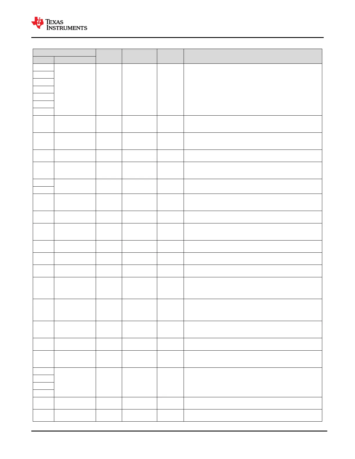
Table 6-1. Pin Functions (continued)
PIN
TYPE CATEGORY POR STATE DESCRIPTION
NO. NAME
C3
No Ball Blank
Ground and no
connect pins
— Unpopulated ball for A1 marker and unpopulated inner ring.
C4
C5
C6
C7
C8
C9
D1 I2C_SDA1 Digital I/O
Digital core I/O
and control pins
Digital input
I
2
C port 1 serial data. Open-drain output. Tie pin to LDO_3V3 or VDDIO
(depending on configuration) through a 10-kΩ resistance when used or
unused.
D10 GPIO2 Digital I/O
Digital core I/O
and control pins
Hi-Z
General purpose digital I/O 2. Float pin if it is configured as a push-pull
output in the application. Ground pin with a 1-MΩ resistor when unused in
the application.
D11 PP_5V0 Power
High-current
power pins
—
5-V supply for VBUS. Bypass with capacitance CPP_5V0 to GND. Tie pin
to GND when unused.
D2 I2C_SCL1 Digital I/O
Digital core I/O
and control pins
Digital input
I
2
C port 1 serial clock. Open-drain output. Tie pin to LDO_3V3 or VDDIO
(depending on configuration) through a 10-kΩ resistance when used or
unused.
D3
No Ball Blank
Ground and no
connect pins
— Unpopulated ball for A1 marker and unpopulated inner ring.
D4
D5
DEBUG_CTL2
(GPIO17, I
2
C ADDR
B5)
Digital I/O
Digital core I/O
and control pins
Hi-Z
General purpose digital I/O 17. At power-up, pin state is sensed to
determine bit 5 of the I
2
C address.
D6 HRESET Digital I/O
Digital core I/O
and control pins
Hi-Z
Active high hardware reset input. Will re-load settings from external flash
memory. Ground pin when HRESET functionality is not used.
D7 GPIO7 Digital I/O
Digital core I/O
and control pins
Hi-Z
General purpose digital I/O 7. Float pin if it is configured as a push-pull
output in the application. Ground pin with a 1-MΩ resistor when unused in
the application.
D8 GND Ground
Ground and no
connect pins
— Ground. Connect all balls to ground plane.
D9 No Ball Blank
Ground and no
connect pins
— Unpopulated ball for A1 marker and unpopulated inner ring.
E1 LDO_BMC Power
Low-current
power pins
—
Output of the USB-PD BMC transceiver output level LDO. Bypass with
capacitance CLDO_BMC to GND.
E10
GPIO5
(HPD RX)
Digital I/O
Digital core I/O
and control pins
Hi-Z
General purpose digital I/O 5. Can be configured as Hot Plug Detect (HPD)
RX when DisplayPort mode supported. Must be tied high or low through
a 1-kΩ pullup or pulldown resistor when used as a configuration input.
Ground pin with a 1-MΩ resistor when unused in the application.
E11
MRESET
(GPIO11)
Digital I/O
Digital core I/O
and control pins
Hi-Z
General purpose digital I/O 11. Forces RESETZ to assert. By default, this
pin asserts RESETZ when pulled high. The pin can be programmed to
assert RESETZ when pulled low. Ground pin with a 1MΩ resistor when
unused in the application.
E2 UART_TX
Digital
output
Port multiplexer
pins
UART_RX
UART serial transmit data. Connect pin to another TPS65982 UART_TX to
share firmware. Connect UART_RX to UART_TX when not connected to
another TPS65982.
E3 No Ball Blank
Ground and no
connect pins
— Unpopulated ball for A1 marker and unpopulated inner ring.
E4
DEBUG_CTL1
(GPIO16, I
2
C ADDR
B4)
Digital I/O
Digital core I/O
and control pins
Hi-Z
General purpose digital I/O 16. At power-up, pin state is sensed to
determine bit 4 of the I
2
C address.
E5
GND Ground
Ground and no
connect pins
— Ground. Connect all balls to ground plane.
E6
E7
E8
E9 No Ball Blank
Ground and no
connect pins
— Unpopulated ball for A1 marker and unpopulated inner ring.
F1 I2C_ADDR Analog I/O
Digital core I/O
and control pins
Analog input
Sets the I
2
C address for both I
2
C ports as well as determine the master and
slave devices for memory code sharing.
www.ti.com
TPS65982
SLVSD02E – MARCH 2015 – REVISED AUGUST 2021
Copyright © 2021 Texas Instruments Incorporated
Submit Document Feedback
7
Product Folder Links: TPS65982

 Loading...


