116
116
NA11 - Manual - 02 - 2009
INSTALLATION
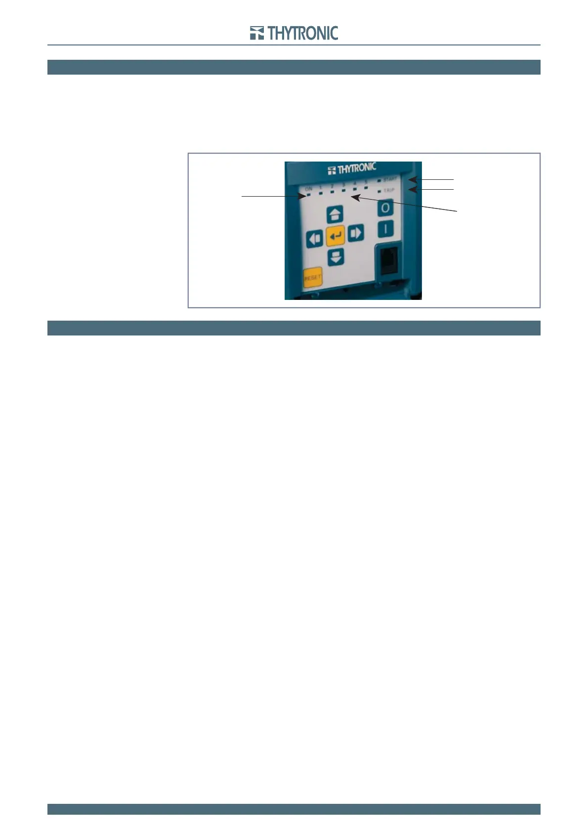
6.5 LED ALLOCATION
Following indicator LEDs are available on the front panel:
LED ON (green): if no diagnostic anomalies are detected, the green LED is turned ON while any fault
is highlighted by fl ashing.
LEDs 1...5 (red) are freely assignable from the user to any protective and/or control functions.
LED START (yellow) committed for start information of any protective functions.
LED TRIP (red) committed for trip information of any protective functions.
6.6 FINAL OPERATIONS
Before energizing the electric board, it is advisable to check that:
The auxiliary voltage in the panel falls within the operative range of Pro_N relays.
The rated current (1 A or 5 A) of the line CT’s corresponds to the setting of Pro_N relays.
All wirings are correct.
All screws are tightly screwed.
•
•
•
•
•
•
•
•
Label_LED
LEDs
ON & Diagnostic
Start
Trip
LED 1...5
user-programmable
Label_LED
LEDs
ON & Diagnostic
Start
Trip
LED 1...5
user-programmable
 Loading...


