77
NA11 - Manual - 02 - 2009
FUNCTION CHARACTERISTICS
Selective block -BLOCK2
[1]
Preface
The logic selectivity function has been developed to the purpose to reduce the clearing times for
faults closes to the source.
The output blocking circuits of one or several Pro_N relays, shunted together, must be connected
to the input blocking circuit of the protection relay, which is installed upwards in the electric plant.
The output circuit works as a simple contact, whose condition is detected by the input circuit of the
upwards protection relay.
The logic selectivity function can be realized through any combination of the following I/O:
One committed pilot wire input BLIN1.
One committed pilot wire output BLOUT1.
One or two independent binary inputs programmed with Block2 Iph, Block2 Iph/IE or
Block2 IE.
One or two independent output relays programmed with BLK2OUT-Iph-K, BLK2OUT-Iph/IE-K
or BLK2OUT-IE-K.
Full diagnostic of pilot wires is only available when committed pilot wire input/outputs are em-
ployed
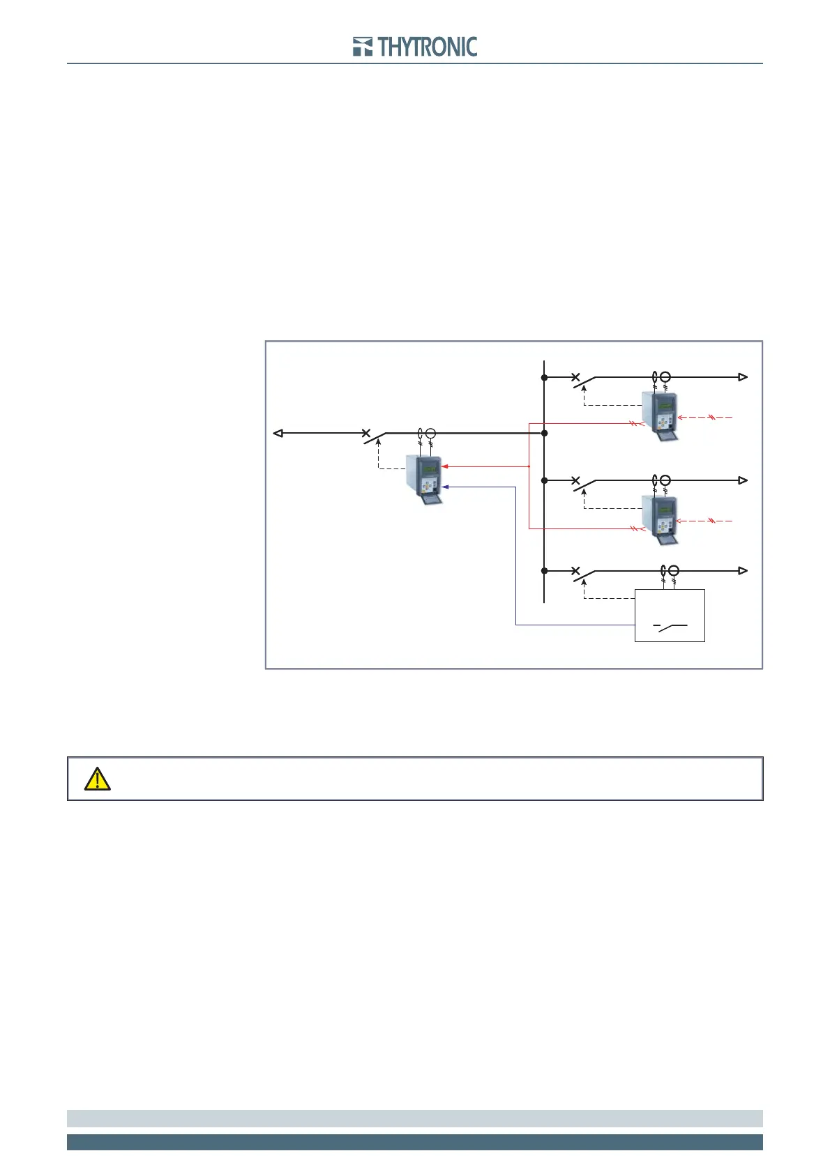
Some protection elements are blocked by downstream devices in the shown schematic diagram.
Input selective block
Use of committed pilot wire input BLIN1:
The input is a polarized wet type powered by internal isolated supply; it must be drive by an output
block signal coming from a Pro-N device or by a free voltage contact..
The protection is blocked off according the selectivity block criteria when the input BLIN1 is active.
The information about phase or phase+earth block may be select programming the ModeBLIN1
parameter inside the Set\Profi le A(or B)\Selective block-BLOCK2\ Selective block IN menus.
Use of binary inputs:
If the xxBLK2IN parameters (enable) are set to ON and a binary input is designed for selective
block (Block2), the protection is blocked off by phase elements (Block2 Iph), by earth elements
(Block2 IE) or by any protection element (Block2 Iph/IE), according the selectivity block criteria,
when the input (IN1 and/or IN2) is active.
The Block2 Iph, Block2 IE and Block2 Iph/IE matching must be assigned to the selected binary
inputs inside the Set\Inputs\Binary input1 and Set\Inputs\Binary input2 menus.
When a binary input is programmed for selective block input, the IN1 tON, IN2 tON, IN1 tOFF and
IN2 tOFF time delays must be reset to zero; the Logic parameters (ON/OFF) must be programmed
in the same way of the related output relay connected with-it..
Operation
For any xxx element, three main conditions can arise:
Start = OFF: the element is at rest (no trip) regardless of the input/output blocks.
Start = ON: the element trips if no selective block input becomes active during the operate time.
Start = ON: if the selective block input (BLIN1 and/or binary input) becomes active, the element
goes in selective block state wherein the operate timer is forced to reset, so the element cannot
trip. After an adjustable time t
B-Iph
(common for phase protection elements) or t
B-IE
(common for
Note 1 The “Logic selectivity” and “Block2“ terms are employed without distinction
•
•
•
•
A)
B)
C)
logica_acc.ai
Logic selectivity
BLIN1
BLIN1
BLIN1
Block2 IPh
BLOUT1
BLOUT1
TRIP I>>
TRIP I>>
TRIP I>>
TRIP I>>
PRO_N
PRO_N
Any device
logica_acc.ai
Logic selectivity
BLIN1
BLIN1
BLIN1
Block2 IPh
BLOUT1
BLOUT1
TRIP I>>
TRIP I>>
TRIP I>>
TRIP I>>
PRO_N
PRO_N
Any device
Never connect power to the block input circuit; the electronic circuit can be demaged
WARNING
Never connect power to the block input circuit; the electronic circuit can be demaged
WARNING
 Loading...


