75
NA11 - Manual - 02 - 2009
FUNCTION CHARACTERISTICS
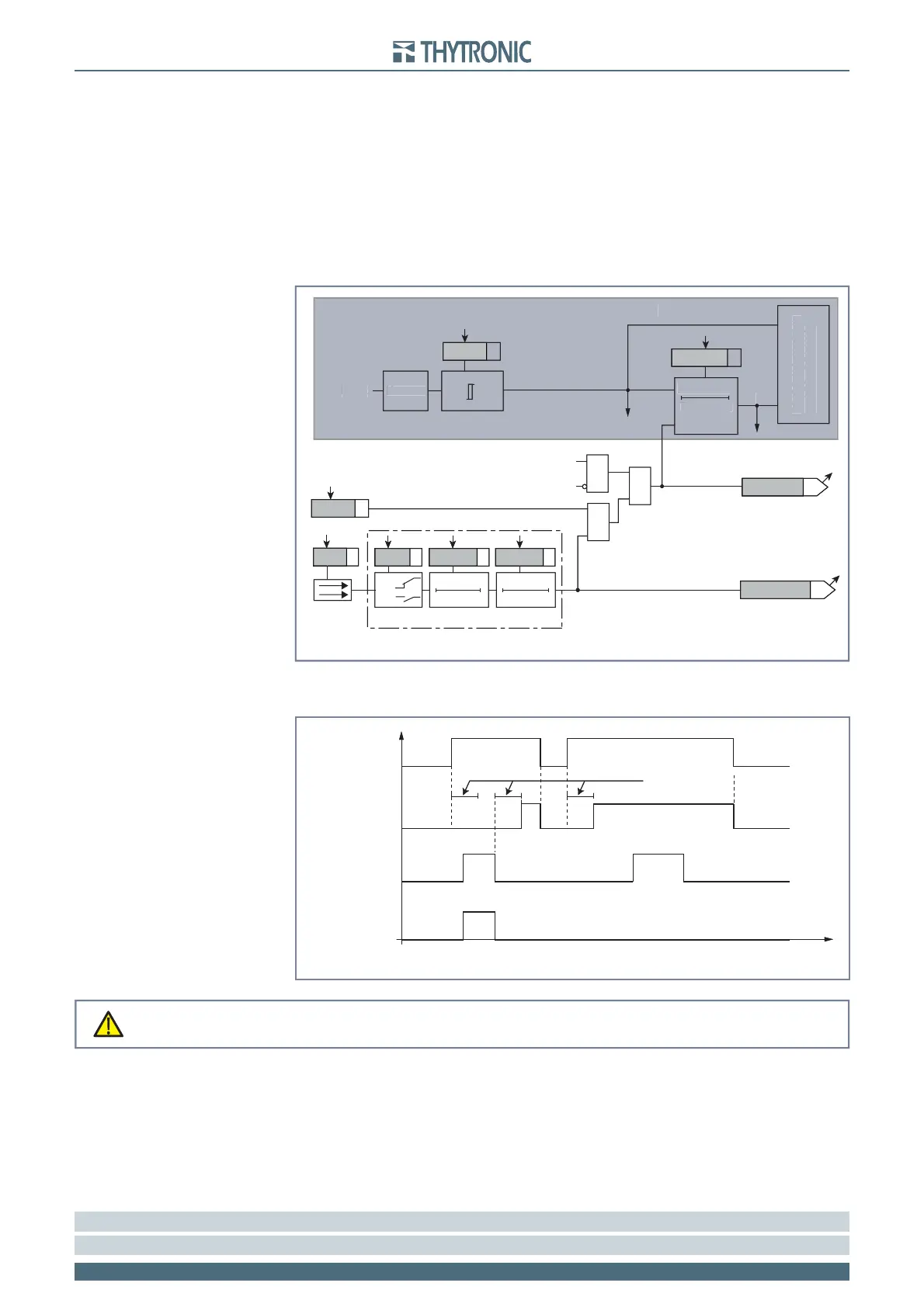
Logical block - BLOCK1
To the purpose to block off the trip of one protection element, the logical block function (Block1) may
be matched with binary inputs.
[1]
The binary-matching may be set inside the Inputs submenu; to the purpose the Block1 parameter
must be selected for INx matching (x=1, 2)
A protective element, where the logical block is enabled, is blocked off whenever the given input is
ON.
For a given protective element, the logical block state is reading available (ThySetter and communi-
cation interfaces); it is ON the following condition are at the same time observed:
Binary input ON
Element start ON
Element Trip OFF.
The logical block it is not liable for any inhibition time-out, so the protective element is disabled for
the whole time when the input is ON.
[2]
Note 1 In the following treatment, the logical block is defi ned as “Logical block” or “Block1”
Note 2 The Block 1 signal forces a timer reset
•
•
•
Blocco_L.ai
RESET
Operate time
0T
Generic protective element
Measure
Input
TRIPPING MATRIX
(LED+RELAYS)
BLK1xxx
Operate time
Threshold
Start
Start
Trip
Trip
&
&
&
Enable (ON≡Enable)
Block1 input (ON≡Block)
Customized Block1 info
Block1 info (internal state)
xxxBLK1
Block1
Block1
T 0
Logic
INx
t
ON
INx
t
ON
INx
t
OFF
T0
n.o.
n.c.
INx
t
OFF
Binary input INx
General logic diagram of the logic block - Block1
RE
ET
Operate tim
eneric protective elemen
easur
n
u
TRIPPIN
MATRIX
LED+RELAY
erate time
Threshol
tart
rip
Blocco_L.ai
RESET
Operate time
0T
Generic protective element
Measure
Input
TRIPPING MATRIX
(LED+RELAYS)
BLK1xxx
Operate time
Threshold
Start
Start
Trip
Trip
&
&
&
Enable (ON≡Enable)
Block1 input (ON≡Block)
Customized Block1 info
Block1 info (internal state)
xxxBLK1
Block1
Block1
T 0
Logic
INx
t
ON
INx
t
ON
INx
t
OFF
T0
n.o.
n.c.
INx
t
OFF
Binary input INx
General logic diagram of the logic block - Block1
Start
Block1 (input)
Block1 (output)
Trip
Operate time
t
Timers-Block1.ai
Logic block timers - Block1
Start
Block1 (input)
Block1 (output)
Trip
Operate time
t
Timers-Block1.ai
Logic block timers - Block1
Activation of any binary input assigned ti logic block (Block1) function effects a block of all the
protective elements where the logic block is enabled
CAUTION
Activation of any binary input assigned ti logic block (Block1) function effects a block of all the
protective elements where the logic block is enabled
CAUTION
 Loading...


