34
34
NA11 - Manual - 02 - 2009
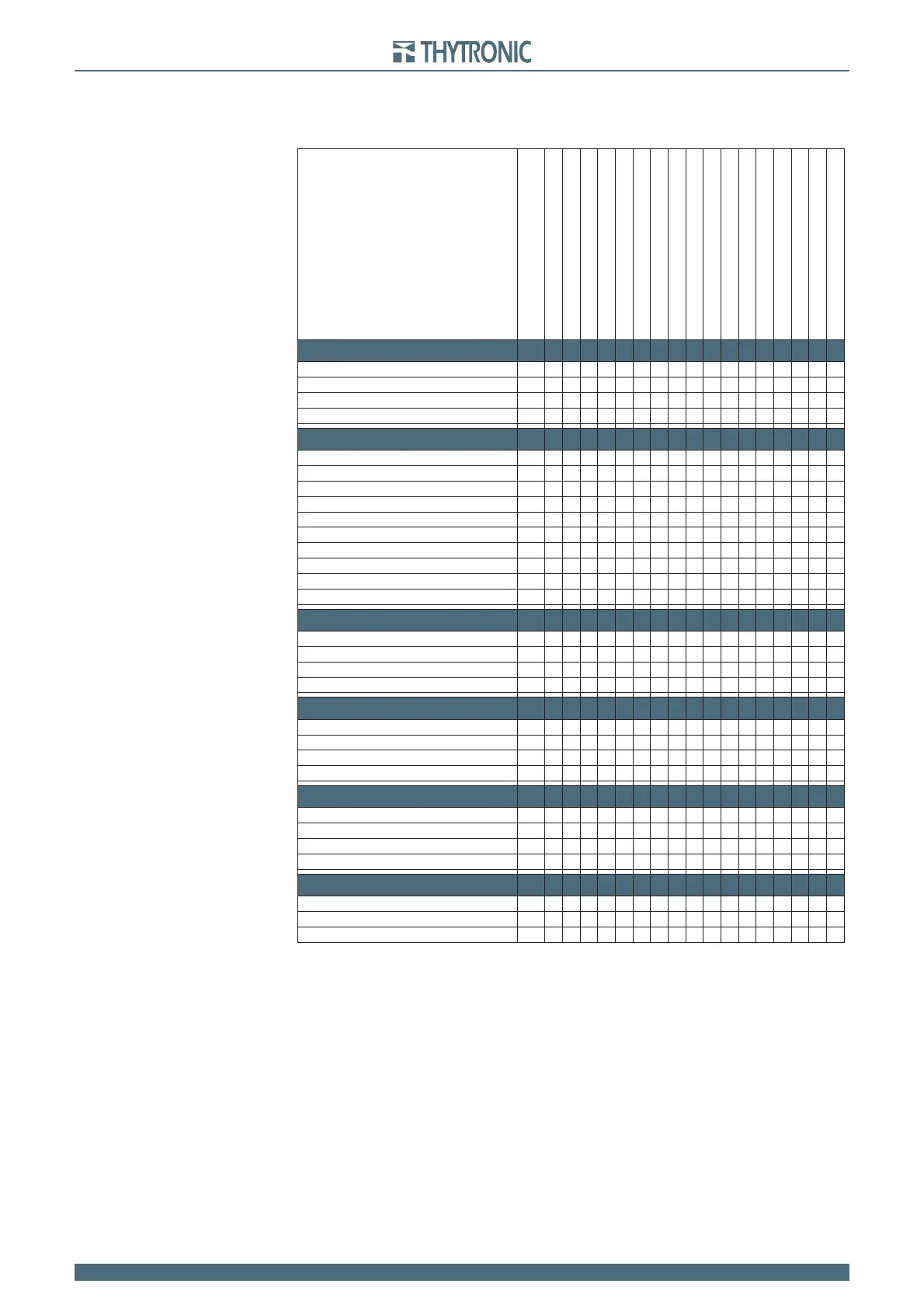
FUNCTION CHARACTERISTICS
Use of measured values
f
i
L1,
i
L2
, i
L3
I
L1,
I
L2
, I
L3
I
L1-2nd,
I
L2-2nd,
I
L3-2nd
i
E
I
E
Temperature (PT1....PT8)
Binary inputs IN1, IN2
Start (START) Relays K1...K6
Trip (TRIP) Relè K1...K6
Start (START) LEDs L1...L5
Trip (TRIP) LEDs L1...L5
Selective block input BLIN1
Selective block output BLOUT1
Cold Load Pickup (CLP)
Second harmonic restraint
Logic block - BLOCK1
Selective block - BLOCK2
PROTECTION
Thermal with Pt100 probes (26)
g
Phase overcurrent (50/51)
g gggggggggg
Residual overcurrent (50N/51N)
g gggggggggg
Breaker failure (BF)
g g ggggg g
CONTROL and MONITORING
CT Monitoring (74CT)
gg
Trip Circuit Supervision (TCS)
g
Second harmonic restraint (2NDH-REST)
g
Logic block (BLOCK1)
g
Selective block (BLOCK2)
ggg
Diagnostic
ggg
Element states
g
Binary input states
g
Selective block state (Block2)
gg
Output relay states
gggg
MEASURES
Frequency
g
Phase currents
g
Residual current
g
Temperature (Pt100 on MPT module)
g
EVENT RECORDER
Event 0
ggggg
Event 1
ggggg
Event ...
ggggg
Event 299
ggggg
FAULT RECORDER
Fault 0
g g ggggg
Fault 1
g g ggggg
Fault ...
g g ggggg
Fault 19
g g ggggg
OSCILLOGRAPHY
Record 1
g ggggggggggg g
Record 2
g ggggggggggg g
Record ...
g ggggggggggg g
 Loading...


