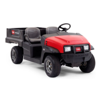
Figure 15
1. Parking brake lever
Choke Control
T he c hok e control is located belo w and to the
right of the operator’ s seat. T o star t a cold engine ,
pull the c hok e control outw ard ( Figure 16 ). After
the engine star ts , regulate the c hok e to k ee p the
engine r unning smoothly . As soon as possible ,
push the control in to the Off position. A w ar m
engine requires little or no c hoking .
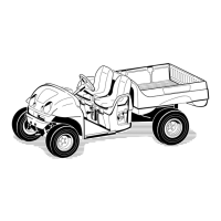
Figure 16
1. Choke 2. Gear shift selector
Gear Shift Selector
T he g ear shift selector has three positions:
forw ard, rev erse , and neutral ( Figure 16 ). T he
engine will star t and r un in any of the three
positions .
Note: If the g ear shift selector is in R ev erse when
the ignition is tur ned on, a buzzer will sound to
w ar n the operator .
Important: Al w ays stop the v ehicle bef or e
changing gear s.
Ignition Switch
T he ignition switc h ( Figure 17 ), used to star t
and stop the engine , has tw o positions: Off
and On. R otate the k ey cloc kwise to the On
position to allo w operation. W hen the v ehicle is
stopped, rotate the k ey countercloc kwise to the
Off position. R emo v e the k ey from the ignition.
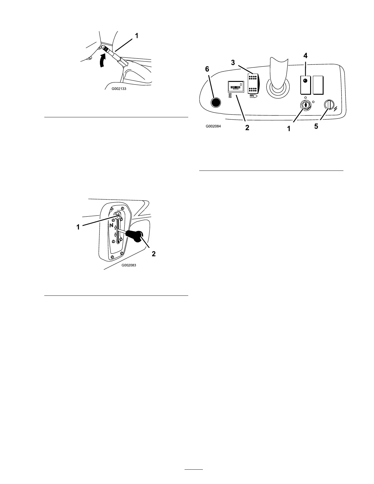
Figure 17
1. Ignition switch 4. Oil light
2. Hour meter
5. Power Point
3. Light switch
6. Horn Button
Hour Meter
T he hour meter ( Figure 17 ) indicates the total
n umber of hours the engine has r un. T he hour
meter star ts to function whenev er the accelerator
is pressed.
Oil Light
T he oil light w ar ns the operator if the engine oil
lev el drops belo w a safe lev el ( Figure 17 ). If the
light comes on and remains lit, the oil lev el should
be c hec k ed and oil added if necessar y; refer to
Chec king the Engine Oil in Operation , pag e 22 .
Note: T he oil light ma y flic k er . T his is nor mal
and no action needs to be tak en.
Light Switch
T og gle the switc h to acti v ate the headlights . Push
to tur n the lights on ( Figure 17 ).
Power Point
Use the po w er point to po w er 12 v olt optional
electrical accessories ( Figure 17 ).
Horn Button
Press the hor n button to sound the hor n
( Figure 17 ).
Fuel Gauge
T he fuel g aug e ( Figure 18 ) sho ws the amount of
fuel in the tank.
19
 Loading...