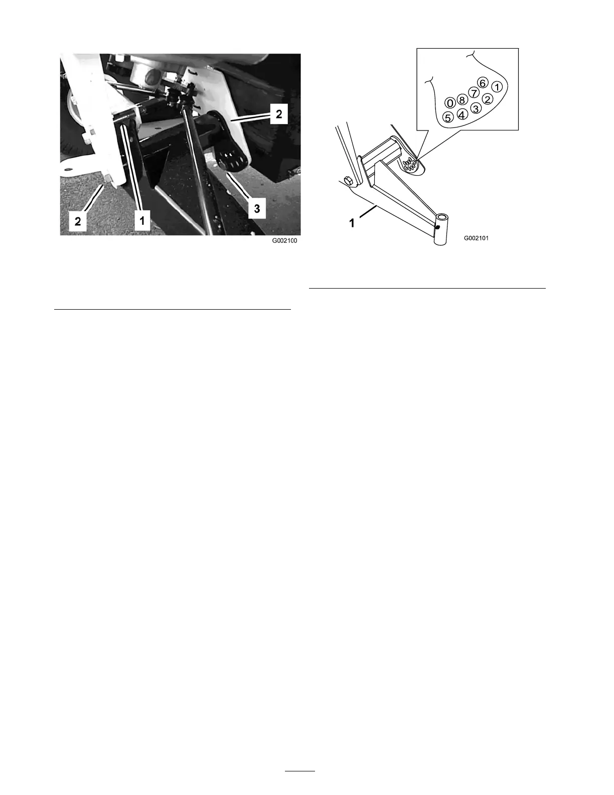
Figure 42
1. Travel limiting bolt 3. Ride height adjustment
bolt
2. Centering bolt
5. R otate the front A-ar m to the desired position
(refer to the note belo w) and re place the ride
height adjustment bolt ( Figure 42 ).
Note: T he A-ar ms are made with r ubber
and ha v e different spring rates . Because of
the different spring rates , the A-ar ms come
adjusted from the factor y based on that spring
rate . Generally the adjustment bolts will be
installed in hole n umber 2, 3, or 4 ( Figure 43 )
and it ma y be different from the left side (dri v er
side) to the right side (passeng er side). If the
A-ar ms look lik e they are sag ging, then they
should be adjusted to the next higher n umber
( Figure 43 ). Eac h hole equals about 3/4 inc h
(19 mm) of adjustment at the wheel. Y ou will
also need to do this if y ou are adding hea vy
attac hments or car r ying hea vy loads often.
Figure 43
1. Left-hand A-arm
6. T or que the ride height adjustment bolt to
135-165 ft-lb (183-224 N ⋅ m).
7. R e place the tra v el limiting bolt ( Figure 42 ).
Note: T he v ehicle ma y need to be lo w ered to
the g round on that side to install the bolt.
8. Tighten and tor que the centering bolts to
240-290 ft-lb (325-393 N ⋅ m).
9. Chec k the ride height at the front tongue per
the dimensions and parameters gi v en at the
beginning of this procedure .
Adjusting Front Wheel
Toe-In
Chec k the front wheel toe-in after ev er y
100 operating hours , or ann ually , whic hev er occurs
first.
T he toe-in should be 1/8-5/8 inc h (3-16 mm) with
the follo wing parameters:
• T he tire pressure should be at 12 psi (83 kP a).
• T he ride height should be cor rect before
setting the toe-in; refer to Adjusting the F ront
Suspension.
• T he v ehicle should be dri v en bac k and for th a
few times to relax the A-ar ms .
• Measure the toe-in with the wheels facing
straight ahead and a 175-225 lb (79-102 kg)
operator in the dri v er’ s seat.
38

 Loading...