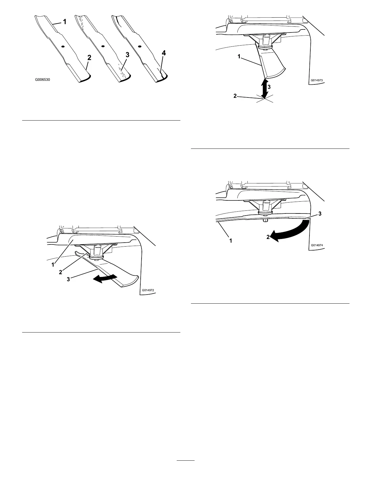
g006530
Figure 58
1. Cutting edge 3. W ear/slot forming
2. Curved area 4. Crack
Checking for Bent Blades
Note: The machine must be on a level surface for
the following procedure.
1. Raise the mower deck to the highest
height-of-cut position.
2. While wearing thickly padded gloves, or other
adequate hand protection, slowly rotate the
blade into a position that allows you to measure
the distance between the cutting edge and the
level surface the machine is on ( Figure 59 ).
g014972
Figure 59
1. Deck 3. Blade
2. Spindle housing
3. Measure from the tip of the blade to the at
surface ( Figure 60 ).
g014973
Figure 60
1. Blade (in position for measuring)
2. Level surface
3. Measured distance between blade and the surface (A)
4. Rotate the same blade 180 degrees so that
the opposing cutting edge is now in the same
position ( Figure 61 ).
g014974
Figure 61
1. Blade (side previously measured)
2. Measurement (position used previously)
3. Opposing side of blade being moved into measurement
position
5. Measure from the tip of the blade to the at
surface ( Figure 62 ).
Note: The variance should be no more than
3 mm (1/8 inch).
42
 Loading...