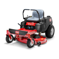
g014973
Figure 62
1. Opposite blade edge (in position for measuring)
2. Level surface
3. Second measured distance between blade and surface (B)
A. If the dif ference between A and B is greater
than 3 mm (1/8 inch), replace the blade with
a new blade; refer to Removing the Blades
( page 43 ) and Installing the Blades ( page
44 ) .
Note: If a bent blade is replaced with a
new blade, and the dimension obtained
continues to exceed 3 mm (1/8 inch), the
blade spindle could be bent. Contact an
Authorized Service Dealer for service.
B. If the variance is within constraints, move to
the next blade.
6. Repeat this procedure on each blade.
Removing the Blades
Replace the blades if they hit a solid object, or if the
blade is out of balance or bent.
1. Hold the blade end using a rag or thickly padded
glove.
2. Remove the blade bolt, curved washer , and
blade from the spindle shaft ( Figure 63 ).
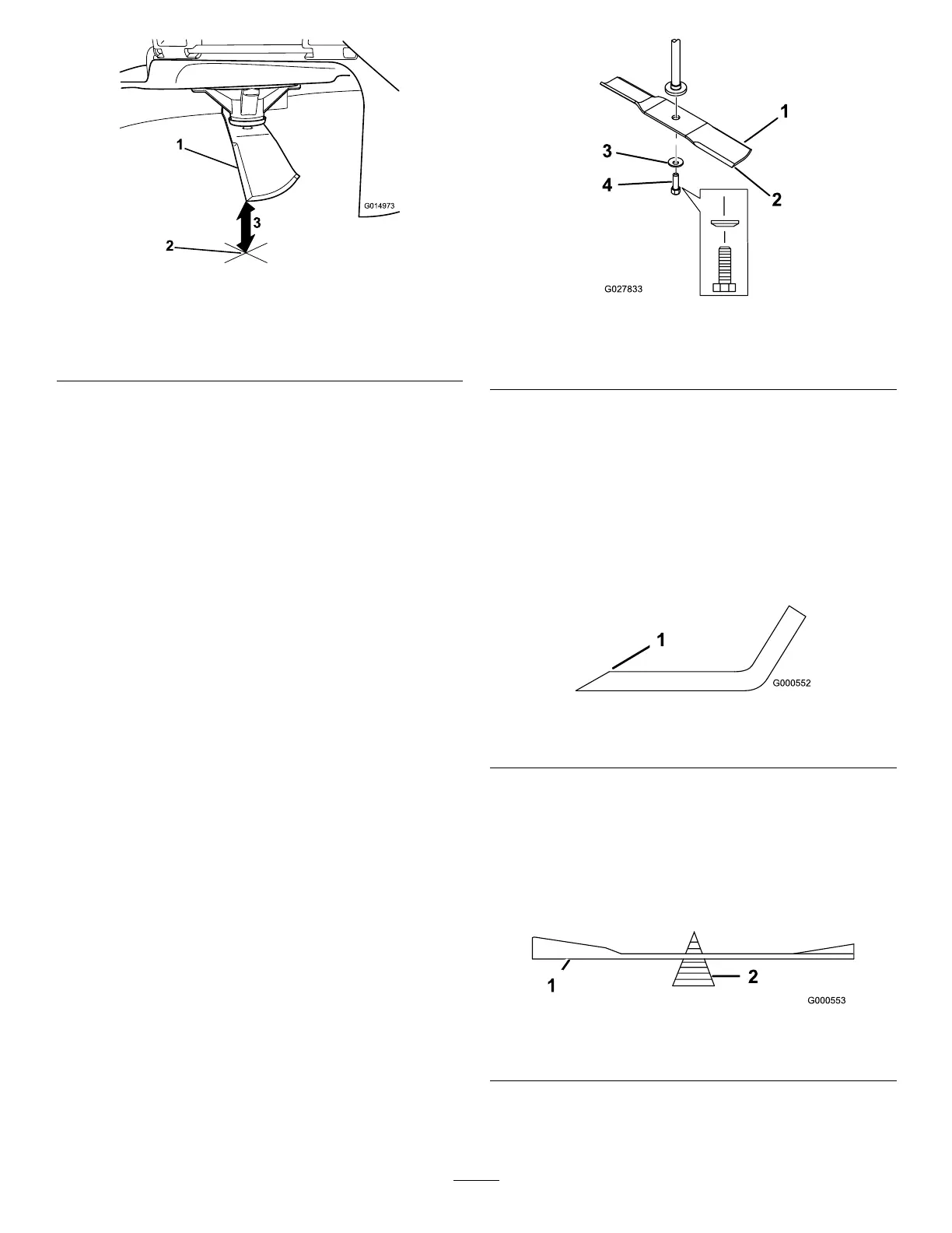
g027833
Figure 63
1. Sail area of the blade 3. Curved washer
2. Blade 4. Blade bolt
Sharpening the Blades
1. Use a le to sharpen the cutting edge at both
ends of the blade ( Figure 64 ).
Note: Maintain the original angle.
Note: The blade retains its balance if the same
amount of material is removed from both cutting
edges.
g000552
Figure 64
1. Sharpen at original angle.
2. Check the balance of the blade by putting it on a
blade balancer ( Figure 65 ).
Note: If the blade stays in a horizontal position,
the blade is balanced and can be used.
Note: If the blade is not balanced, le some
metal of f the end of the sail area only ( Figure 64 ).
g000553
Figure 65
1. Blade 2. Balancer
3. Repeat this procedure until the blade is
balanced.
43
 Loading...