Workman GTX Gasoline Page 5 − 9 Electrical System
Component Testing
For accurate resistance and/or continuity checks, elec-
trically disconnect the component being tested from the
circuit (e.g. unplug the wire harness connector from the
key switch before doing a continuity check on the
switch).
NOTE: For engine electrical component testing infor-
mation, see the Kohler COMMAND PRO
CH260−CH440 Service Manual for machines with car-
bureted engines and the Kohler COMMAND PRO EFI
ECH440 & ECH440LE Service Manual for machines
with fuel injected (EFI) engines.
CAUTION
When testing electrical components for continu-
ity with a multimeter (ohms setting), make sure
that power to the circuit has been disconnected.
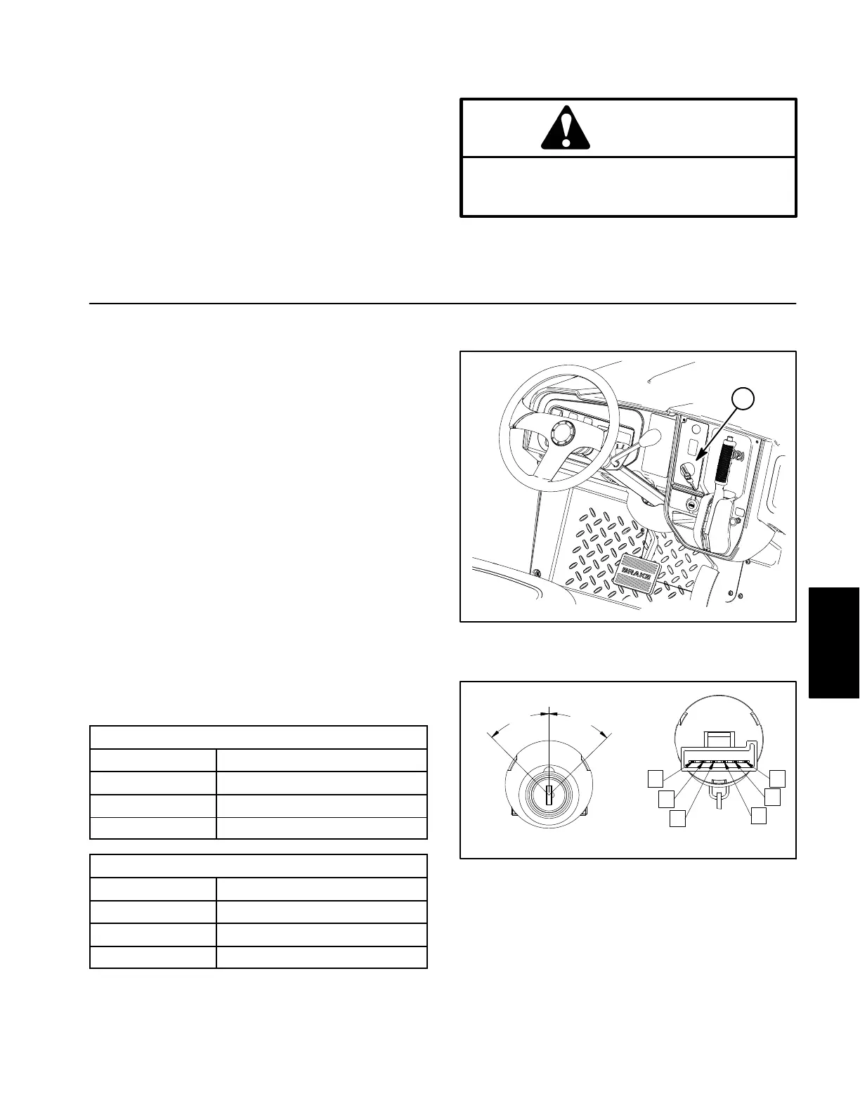
Key Switch
The dash mounted key switch used on the Workman
has three (3) switch positions (OFF, ON AND START)
and six (6) switch terminals. The switch terminals are
identified as shown in Figure 8.
Testing
1. Park vehicle on a level surface, shut engine off and
engage the parking brake. Remove key from the key
switch.
2. Raise hood to allow access to wire harness connec-
tions for key switch. Disconnect wire harness connector
from the key switch.
3. With the use of a multimeter (ohms setting), the key
switch functions may be tested to determine whether
continuity exists between the various terminals for each
switch position. The switch terminals are marked as
shown in Figure 8. The circuitry of the switch is shown
in the chart below. Verify continuity between switch ter-
minals.
Machine serial number below 401400000
POSITION CIRCUITS
OFF NONE
ON B + C + F, D + E
START A + B + C
Machine serial number above 401400000
POSITION CIRCUITS
OFF E + F
ON A + B
START A + B, C + D
4. Replace key switch if testing determines that the
switch is faulty.
Figure 7
1. Key switch
1
Figure 8
FRONT VIEW
OFF
ON
45
o
45
o
START
A
B
C
D
E
F
REAR VIEW
5. If key switch tests correctly and circuit problem still
exists, check wire harness (see electrical schematic and
wire harness drawing in Chapter 7 − Electrical Draw-
ings).
6. After key switch testing is complete, connect wire
harness connector to the switch. Lower and secure front
hood.
Electrical
System

 Loading...