Workman GTX Gasoline Page 5 − 19 Electrical System
Accelerator Pedal Switch
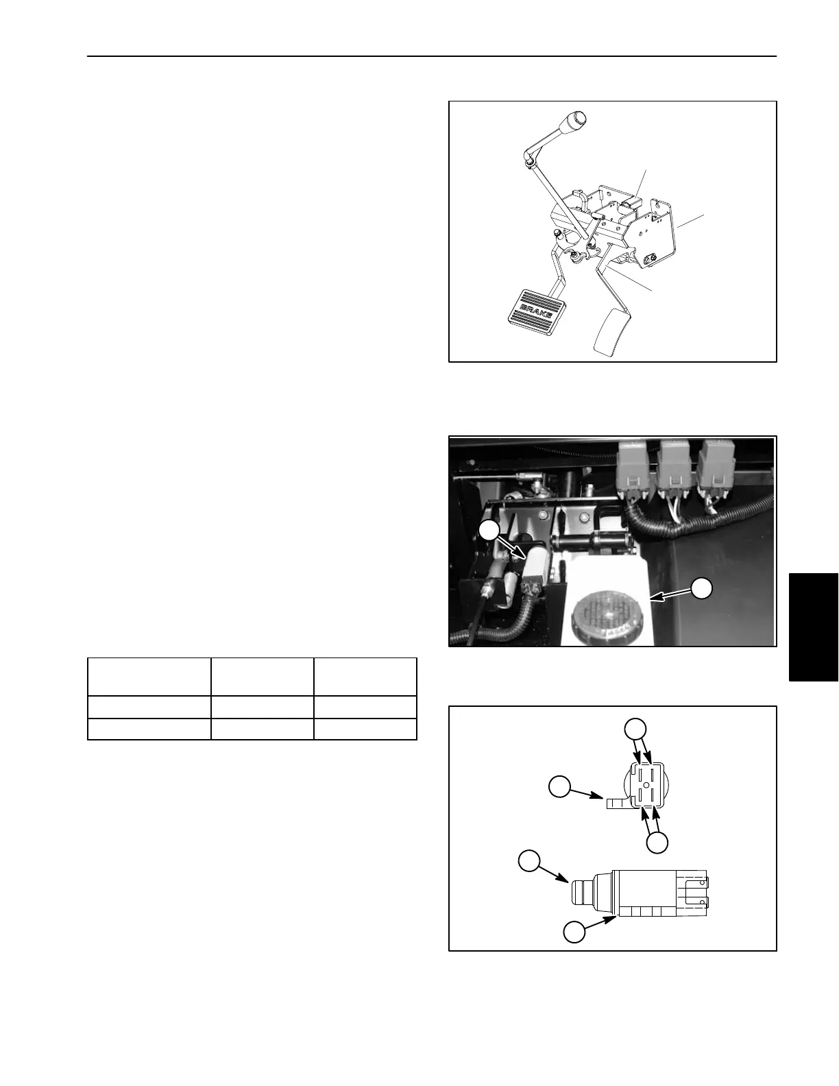
The accelerator pedal switch is a four (4) terminal, two
(2) circuit switch. The switch is used to determine if the
accelerator pedal is depressed or not when starting the
engine via the accelerator pedal. The switch is attached
to the pedal mount next to the brake master cylinder
(Fig. 22).
When the accelerator pedal is pushed, the switch allows
current flow to the start/run solenoid and hour meter and
also provides an open circuit to the engine ignition sys-
tem to allow the magneto ignition to operate. With the
accelerator pedal released, the switch provides a
grounding circuit for the engine ignition system and also
prevents current flow to the start/run solenoid and hour
meter.
Testing
1. Park vehicle on a level surface, stop engine, engage
parking brake and remove key from the key switch.
Place vehicle shift lever in the NEUTRAL position.
2. Raise hood to gain access to accelerator pedal
switch (Fig. 23).
3. Unplug wire harness connector from accelerator
pedal switch. Note that wire harness connector is keyed
to fit correctly onto the pedal switch.
4. With the use of a multimeter (ohms setting), the
switch functions may be tested to determine whether
continuity exists between the switch terminals for both
switch positions. Verify continuity between switch termi-
nals using the following table:
PLUNGER
POSITION
CONTINUITY
NO
CONTINUITY
IN NO Terminals NC Terminals
OUT NC Terminals NO Terminals
5. Replace switch if testing determines that it is faulty.
6. After testing is complete, plug wire harness connec-
tor to accelerator pedal switch. Use dielectric gel to pre-
vent corrosion of connection terminals. To ensure
complete coating of switch terminals, liberally apply gel
to switch terminals and wire harness connector, plug
connector to switch, unplug connector, reapply gel to
both surfaces and reconnect harness connector to
switch. Connectors should be thoroughly packed with
gel for effective results.
7. Lower and secure hood.
1. Accelerator pedal
2. Pedal mount
3. Accelerator switch
Figure 22
1
2
3
1. Accelerator pedal switch 2. Brake master cylinder
Figure 23
1
2
1. NO terminals
2. NC terminals
3. Switch plunger
4. Mounting tab
Figure 24
END VIEW
SIDE VIEW
4
4
3
SWITCH
SWITCH
2
1
Electrical
System

 Loading...