4. Mo v e the motion control lev er forw ard and
rev erse , then bac k to neutral. T he wheel m ust
stop tur ning or slightly cree p in rev erse .
5. Open the throttle to fast. Mak e sure the wheel
remains stopped or slightly cree ps in rev erse ,
adjust if necessar y .
6. Tighten the loc kn uts at the ball joints
( Figure 66 ).
Electrical system will not perf or m pr oper
safety shut of f with jumper wir e installed.
• R emo v e jumper wir e fr om wir e
har ness connector and plug
connector into seat s witch when
adjustment is completed.
• Nev er operate this unit with jumper
installed and seat s witch bypassed.
7. After both pump neutrals are set, shut off the
mac hine .
8. R emo v e the jumper wire from the wire har ness
connector and plug the connector into the seat
switc h.
9. Install the seat rod and lo w er the seat into
position.
10. R emo v e the jac k stands .
Mower Deck
Maintenance
Leveling the Mower at Three
Positions
Important: T her e ar e onl y thr ee measuring
positions needed to lev el the mo w er .
Setting Up the Machine
1. P osition mo w er on a flat surface .
2. Diseng ag e the PTO , mo v e the motion control
lev ers to the neutral loc k ed position and set
the parking brak e .
3. Stop the engine , remo v e the k ey , and w ait for
all mo ving par ts to stop before lea ving the
operating position.
4. Chec k tire pressure of all four tires . If needed,
adjust to 13 psi (90 kP a)
5. Lo w er the mo w er to the 3 inc h (76 mm)
height-of-cut position.
6. Inspect the four c hains . T he c hains need to
ha v e tension.
• If one rear c hain is loose , lo w er (loosen) the
front suppor t ar m on the same side . R efer to
Adjusting the F ront-to-R ear Mo w er Pitc h.
• If one front c hain is loose , raise (tighten) the
front suppor t ar m for that c hain. R efer to
Adjusting the F ront-to-R ear Mo w er Pitc h.
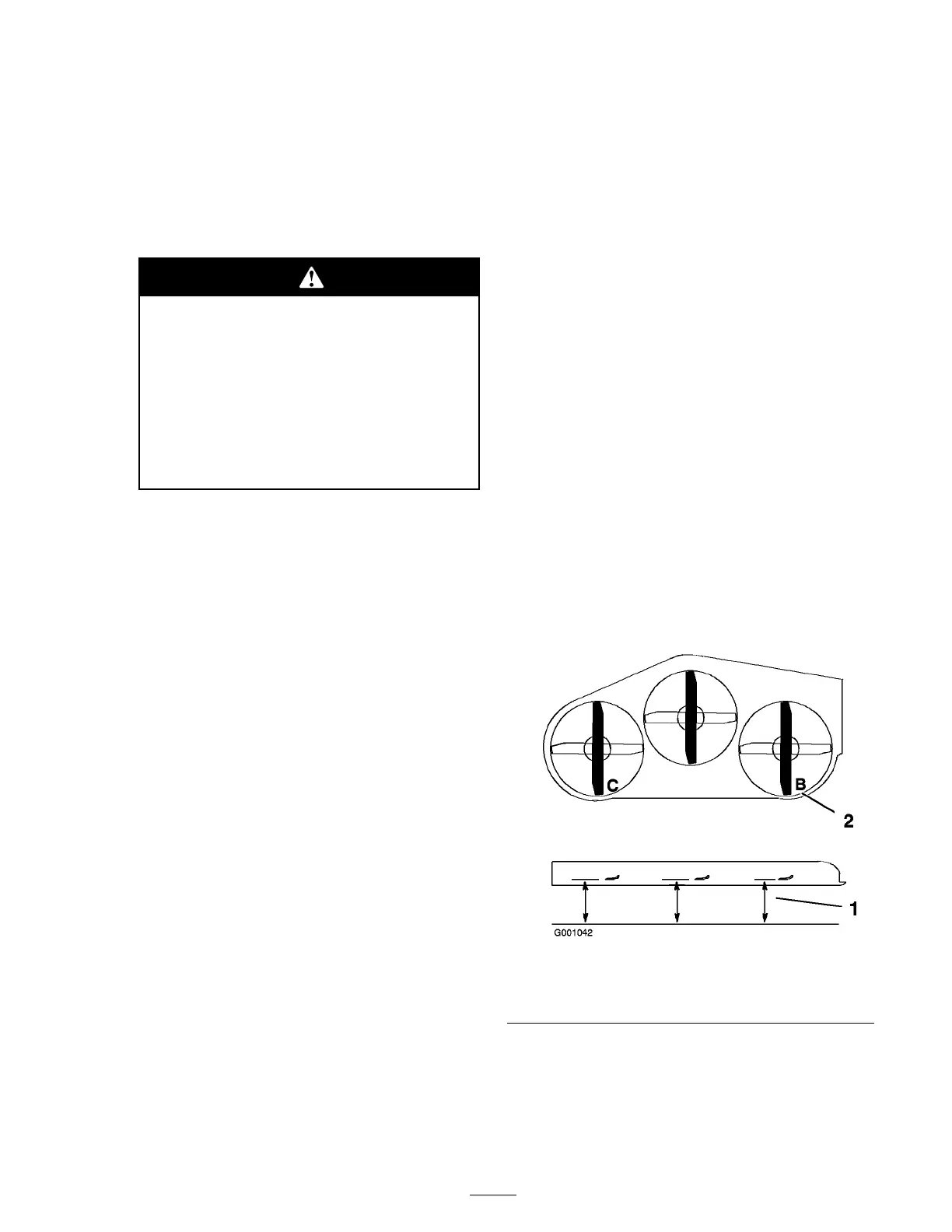
Leveling the Mower Side-to-Side
1. P osition the right blade front-to-rear
( Figure 67 ).
2. Measure the right blade at the B location, from
a lev el surface to the cutting edg e of the blade
tip ( Figure 67 ).
3. R ecord this measurement. T his measurement
needs to be 3-1/8 to 3-1/4 inc hes .
4. P osition the left blade front-to-rear ( Figure 67 ).
5. Measure the left blade at the C location
( Figure 67 ), from a lev el surface to the cutting
edg e of the blade tip .
6. R ecord this measurement. T his measurement
needs to be 3-1/8 to 3-1/4 inc hes .
Figure 67
1. Measure here from blade
to hard surface
2. Measure at B and C
7. If the measurements at positions B or C are
not cor rect, loosen the bolt attac hing the rear
c hain to the rear suppor t ar m ( Figure 68 ).
8. Loosen the jam n ut under the rear suppor t
ar m and adjust the adjustment bolt to g et
51
 Loading...


