2. Stop the engine , remo v e the k ey , and w ait for
all mo ving par ts to stop before lea ving the
operating position.
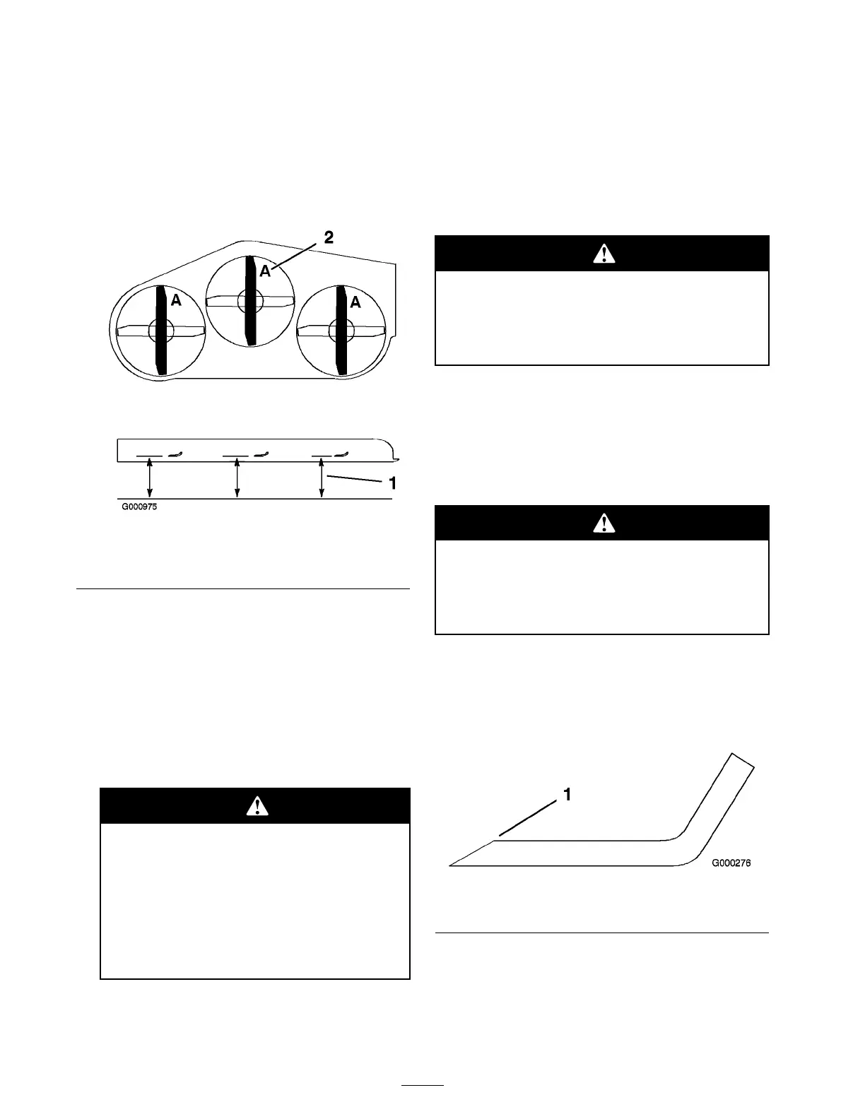
3. R otate the blades until the ends face forw ard
and bac kw ard ( Figure 72 ). Measure from a
lev el surface to the cutting edg e , position A , of
the blades ( Figure 72 ). Note this dimension.
Figure 72
1. Measure here from blade
to hard surface
2. Position A
4. R otate the opposite ends of the blades forw ard.
5. Measure from a lev el surface to the cutting
edg e of the blades at the same position as
in ste p 3 abo v e . T he difference betw een the
dimensions obtained in ste ps 3 and 4 m ust not
ex ceed 1/8 inc h (3 mm). If this dimension
ex ceeds 1/8 inc h (3 mm), the blade is bent
and m ust be re placed; refer to R emo ving the
Blades and Installing the Blades .
A blade that is bent or dama ged could
br eak apar t and could seriousl y injur e or
kill y ou or bystander s.
• Al w ays r eplace bent or dama ged
blade with a new blade.
• Nev er file or cr eate shar p notches in
the edges or surf aces of blade.
Removing the Blades
Blades m ust be re placed if a solid object is hit,
if the blade is out of balance or is bent. T o
ensure optim um perfor mance and contin ued
safety confor mance of the mac hine , use g en uine
T oro re placement blades . R e placement blades
made b y other man ufacturers ma y result in
non-confor mance with safety standards .
Contact with a shar p blade can cause serious
injur y .
W ear g lo v es or wrap shar p edges of the
blade with a ra g .
1. Hold the blade end using a rag or
thic kly-padded glo v e .
2. R emo v e the blade bolt, spring disk and blade
from the spindle shaft ( Figure 75 ).
Sharpening the Blades
W hen shar pening blade, pieces of blade
could be thr o wn and cause serious injur y .
W ear pr oper ey e pr otection when shar pening
blade.
1. Use a file to shar pen the cutting edg e at both
ends of the blade ( Figure 73 ). Maintain the
original angle . T he blade retains its balance if
the same amount of material is remo v ed from
both cutting edg es .
Figure 73
1. Sharpen at original angle
2. Chec k the balance of the blade b y putting it on
a blade balancer ( Figure 74 ). If the blade sta ys
in a horizontal position, the blade is balanced
and can be used. If the blade is not balanced,
file some metal off the end of the sail area only
54
 Loading...


