AC-SVX001A-EN
39
WWAARRNNIINNGG
PPrrooppeerr FFiieelldd WWiirriinngg aanndd GGrroouunnddiinngg
RReeqquuiirreedd!!
FFaaiilluurree ttoo ffoollllooww ccooddee ccoouulldd rreessuulltt iinn ddeeaatthh oorr
sseerriioouuss iinnjjuurryy..
AAllll ffiieelldd wwiirriinngg MMUUSSTT bbee ppeerrffoorrmmeedd bbyy qquuaalliiffiieedd
ppeerrssoonnnneell.. IImmpprrooppeerrllyy iinnssttaalllleedd aanndd ggrroouunnddeedd
ffiieelldd wwiirriinngg ppoosseess FFIIRREE aanndd EELLEECCTTRROOCCUUTTIIOONN
hhaazzaarrddss.. TToo aavvooiidd tthheessee hhaazzaarrddss,, yyoouu MMUUSSTT ffoollllooww
rreeqquuiirreemmeennttss ffoorr ffiieelldd wwiirriinngg iinnssttaallllaattiioonn aanndd
ggrroouunnddiinngg aass ddeessccrriibbeedd iinn NNEECC aanndd yyoouurr llooccaall//
ssttaattee//nnaattiioonnaall eelleeccttrriiccaall ccooddeess..
NNOOTTIICCEE
UUssee CCooppppeerr CCoonndduuccttoorrss OOnnllyy!!
FFaaiilluurree ttoo uussee ccooppppeerr ccoonndduuccttoorrss ccoouulldd rreessuulltt iinn
eeqquuiippmmeenntt ddaammaaggee aass tthhee eeqquuiippmmeenntt wwaass nnoott
ddeessiiggnneedd oorr qquuaalliiffiieedd ttoo aacccceepptt ootthheerr ttyyppeess ooff
ccoonndduuccttoorrss..
IImmppoorrttaanntt::
To prevent control malfunctions, do not run low
voltage wiring (<30 V) in conduit with conductors
carrying more than 30 volts.
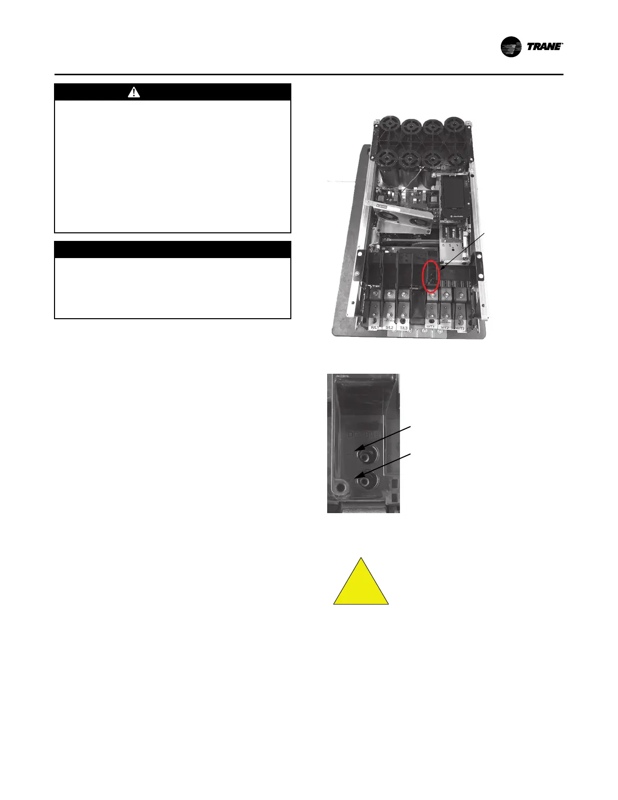
Adaptive Frequency™™ Drive Capacitor
Discharge
After disconnecting input power, wait five (5) minutes
for the DC capacitors to discharge.
Using voltmeter, measure voltage on bus at bus access
points. See figures below for location of bus access
points, and details. Capacitors are fully discharged
when voltage across these plus (+) and minus (-) points
measures 0 VDC.
Figure 19. AFD dc bus measurement location
For units with nitrogen
charge option (model
number digit 15 = 2), the unit
must NOT have shore power,
or unit power applied until
the unit has been charged.
Applying power will drive
EXV valves closed, and will
inhibit sufficient vac for unit
charging.
Installer-Supplied Components
Customer wiring interface connections are shown in
the electrical schematics and connection diagrams that
are shipped with the unit. The installer must provide
the following components if not ordered with the unit:
IInnssttaallllaattiioonn EElleeccttrriiccaall
 Loading...


