26 AFDH-SVN01A-EN
AFDH Drive Package Specifications
D-Frame and E-Frame Drive unit components
Drive unit component parts housed within the custom enclosure
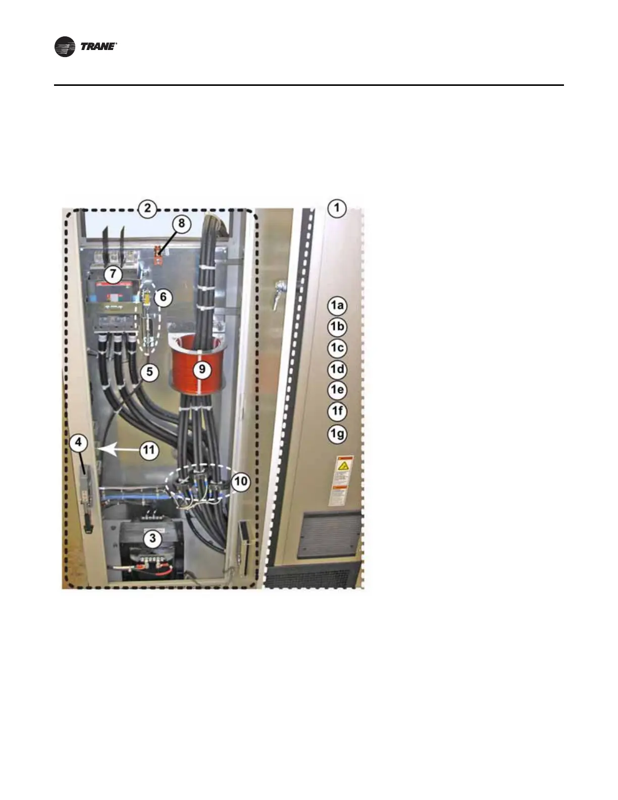
Figure 12. Mounting location of D and E-Frame custom enclosure parts
1.Right-hand cabinet section houses the
TR1 drive module for the unit. For the part
numbers of the components housed
within the left-hand custom enclosure
section of the unit by drive model size,
refer to the tables listed below:
a.D-Frame 302 amp drive see Tabl e 6
b.D-Frame 361 amp drive see Tab le 7
c.D-Frame 443 amp drive see Tabl e 8
d.E-Frame 540 amp drive see Tab le 9
e.E-Frame 590 amp drive see Tab l e 10
f.E-Frame 678 amp drive see Tab le 11
g.E-Frame 730 amp drive see Tab le 1 2
2.Custom enclosure section of unit
3.Transformer (4 KVA)
4.Circuit breaker handle
5.Circuit breaker cable
6.Circuit breaker mechanism
7. C i r c u i t b r e a k e r
8.Ground lug
9.Choke
10.Current transformers (CTs)
11.To view the components attached to the
left interior wall of the enclosure, go to
the next page in the manual
 Loading...


