Installation - Mechanical
UNT-SVX041D-EN 19
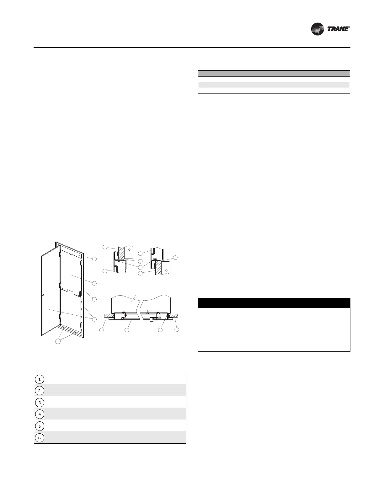
Return Air Panel (Perimeter Return Air
Panel) with Cover
1. If the drywall has not been installed flush with the outer
edge of the collar on the unit and if the gap between the
inner surface of the drywall and the outer edge of the
collar exceeds one-half inch, the opening will have to
be sleeved (not provided by the factory).
2. The covers are shipped with the unit. Remove the
control box and fan cover from the unit. Insert the
return air panel and install six sheet metal screws as
shown in Figure 5. Do not over-tighten the screws as
this might distort the door frame.
3. Insert the fan cover into the frame of the return air door
with 45 degree flanges and then secure it by fitting
sheet metal screws in the frame.
4. Mount the control box cover in the same way as the
motor cover.
Note: This type of return air door requires a 1 inch deep
collar on the front of the fan coil unit. Drywall can
be attached directly to the front of the unit after
mounting this door.
Thermostat Installation
Unit mounted thermostat
Connect the wires from the thermostat to the wire harness
inside the electrical box using the plug provided or by
connecting directly to the terminal strip on the CSTI board.
Mount the thermostat to the drywall using a standard mud
flap or control box.
Remote mounted thermostat
Run low voltage wires from the 24V thermostat on the wall
back to the thermostat plug inside the unit. Ensure that the
guidelines described in the “Power Connection,” section
on page 28 are followed when installing thermostats.
Typical Installation Sequence
Typical Fan Coil Unit
1. A rectangular opening is made in the floor slab, usually
sleeved before pouring the floor. Refer to the catalog or
submittals for sizes.
2. Rotate the unit from the horizontal position to vertical
so that the bottom end of the risers insert into the
expanded end of the risers on the unit below.
Approximately two inches is allowed in the riser length
for the depth of the insertion. Shim the unit plumb.
3. Before making the joint, ensure that the run outs from
the supply and return risers are centered in the slots in
the cabinet. If this is not done there is considerable risk
of distorting the run out when the riser expands or
contracts causing the run out to deform on the edge of
the slot in the cabinet sheet metal. Also ensure that all
riser stub outs are at 90° to the cabinet so that the drain
hose is not kinked and the run-outs do not get
deformed.
4. Riser anchoring is required for two main purposes. The
risers are anchored to the floor slab at one or more
points in the height of the building so that they do not
slip down under gravity. The second reason is to
spread the expansion in opposite directions from the
anchor point. If there are expansion loops included in
Figure 5. Return air panel - framed out drywall
Table 7. Return air panel - framed out drywall callouts
Return air door
Fan cover for air blockoff
Control box cover for air blockoff
1 inch deep collar around return air opening on fan coil unit
1 inch drywall
Screw
Fan coil unit
5
61
5
1
2
1
3
5
6
6
1
4
6
5
4
Top side section Bottom side section
Table 8. Nominal return air door size
Size Door size (inches)
300, 400 18 x 56
600. 800 21 x 56
1000, 1200 25 x 56
NOTICE
Equipment Damage!
Failure to follow instructions below could result in
equipment damage. Ensure the horizontal run-out from
each riser is centered in the cabinet slot and at 90
degrees as it enters the cabinet prior to soldering the
risers.
 Loading...