Diagnostics and Troubleshooting
UNT-SVX041D-EN 75
Testing Battery Status
Initiate a battery status test as follows:
• On the WZS, push the Test button on the sensor (see
location on Figure 60). LED5 on the sensor responds by
indicating the level of battery strength, as shown in the
table below.
• On the WDS, push the Test button on the sensor (see
location on Figure 61). In response, a battery test
symbol appears on the display. The symbol shown
indicates battery life expectancy (see Table 37).
24 V Power Status Indicator
LED5 on the receiver of all models (see Figure 59 , page 72)
lights and stays constantly On when 24 V power is normal.
Check Signal Strength on a Site
Use the wireless sensor system to check the signal
strength on a site.
1. Power up a receiver with a 24 V transformer (user
supplied).
2. Associate the sensor to a receiver of the same model
intended for the job.
3. Place the receiver at the desired location.
4. Place or hold the sensor at the desired location.
5. Press the Test button (S5) on the sensor and observe
the signal strength as indicated by LED1, LED2, and
LED3 on model WZS (see Figure 60), and on the
display on model WDS (see Figure 61 , page 73).
For more information on interpreting the LEDs and the
display symbols that indicate signal strength, see “Testing
Signal Strength,” page 74.
Replacing Sensor Batteries
Sensor battery type, length of life, and installation are
addressed in this section.
Battery Type
Use two non-rechargeable 1.5 V lithium AA batteries in the
sensor. To maintain UL rating, use only UL-listed lithium
batteries. The sensor ships with Energizer
®
L91 batteries
already installed. Replacement batteries are available at
Trane Service Parts Centers (p/n X13770035010) or other
local suppliers.
Battery Life
Battery life is five years under normal conditions. If the
sensor is not used for an extended period of time, do one
of the following:
• Set the sensor address to 000 to place the sensor into
a low-power hibernation mode.
• Remove the batteries.
Table 36. Battery status indicated by LED5 on the wireless zone sensors
User action LED state Indicates...
Press Test
button
Solid green for 5 seconds Battery is adequate for proper operation.
Solid red for 5 seconds 25% battery life left. Batteries should be replaced.
No light Batteries life expired or not installed properly, or sensor is defective.
None
Blinking red: 1-blink pattern
(a)
repeated 5 times.
Cycle repeats every 15 minutes.
Approximately 14 days of operation remain before the battery is too weak
to power the sensor.
(a) Blink pattern is On for 1/4 s, Off for 3/4 s, with 2 s Off between repetitions.
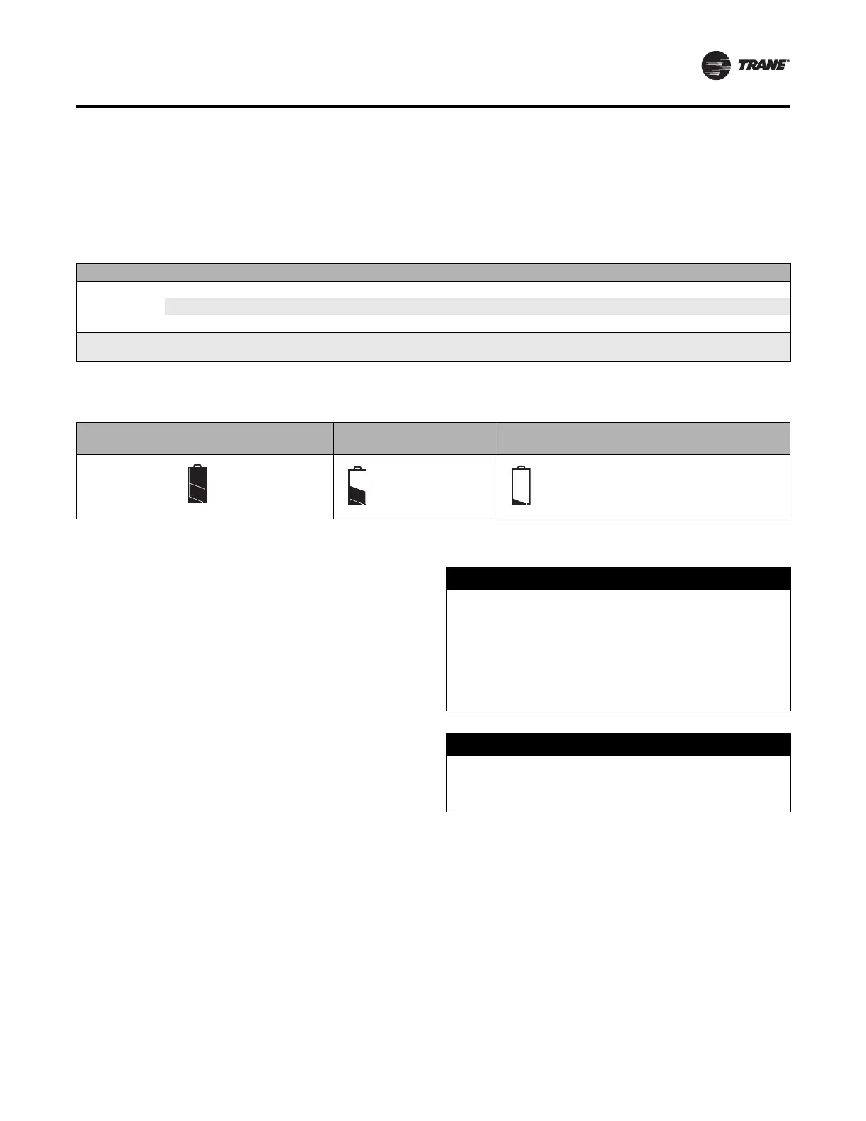
Table 37. Battery status shown on the wireless display sensor
User action
Battery test
symbol Indicates...
Battery test
symbol Indicates...
Battery test
symbol Indicates...
Press Test
button
Full battery
power.
50percent battery
life left.
25 percent battery life left. Replace batteries.
Flashing symbol indicates that approximately
14 days of operation remain before the battery
is too weak to power the sensor.
NOTICE
Battery Damage!
Failure to follow instructions below could result in
battery leakage and, in some cases, cause the safety
release vent to open.
Do NOT attempt to recharge the batteries. The batteries
are manufactured in a ready-to-use state and are NOT
designed for recharging.
NOTICE
Sensor Damage!
Do not attempt to hook up the sensor to a power
supply as it could result in sensor damage.
 Loading...