Installation - Controls
52 UNT-SVX041D-EN
Wired Zone Sensor
Refer to the unit wiring schematic for specific wiring
details and point connections.
1. Note the position of the setpoint adjustment knob and
gently pry the adjustment knob from the cover using
the blade of a small screwdriver.
2. Insert the screwdriver blade behind the cover at the top
of the module and carefully pry the cover away from
the base.
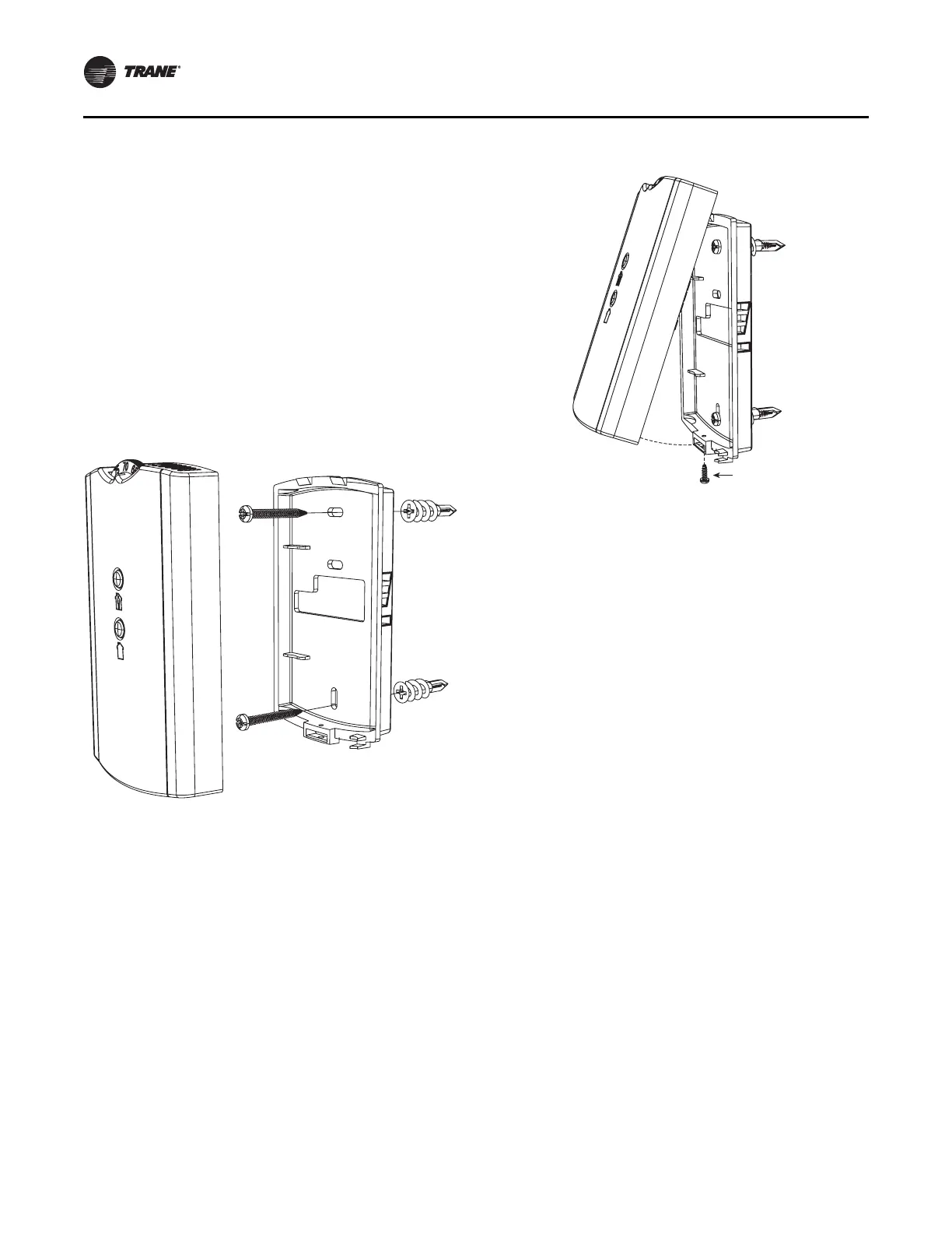
3. To mount the sensor back plate: (see the figure below).
a. Hold the back plate against the mounting surface
and mark the screw locations.
b. Secure the back plate against the mounting surface
using included hardware.
4. To install the zone sensor module to a standard
junction box:
a. Level and install a 2 x 4-inch junction box (installer
supplied) vertically on the wall.
b. Pull the control wires through the cutout. Attach the
module to the wall using the screws provided.
5. Strip the insulation on the interconnection wires back
0.25-inch and connect to TB1 (for wired sensors).
6. Screw down the terminal blocks (for wired sensors).
7. To replace the cover:
a. Hook the cover over the top of the back plate. Apply
light pressure to the bottom of the cover until it
snaps in place.
b. Install the security screw into the bottom of the
cover if desired (see the following figure).
Wireless Zone Sensors
1. Note the position of the setpoint adjustment knob and
gently pry the adjustment knob from the cover using
the blade of a small screwdriver.
2. Insert the screwdriver blade behind the cover at the top
of the module and carefully pry the cover away from
the base.
3. To mount the sensor back plate: (see Figure 42)
a. Hold the back plate against the mounting surface
and mark the screw locations.
b. Secure the back plate against the mounting surface
using included hardware.
4. To replace the cover:
a. Hook the cover over the top of the back plate. Apply
light pressure to the bottom of the cover until it
snaps in place.
b. Install the security screw into the bottom of the
cover if desired (see Figure 43).
Note: For more detailed information for wireless sensors,
please see BAS-SVX04*-EN.
Receivers
Receivers ship installed on the unit. To remove the
receiver, press in the retention tabs on the underside of the
receiver enclosure (see Figure 44) and push upward.
Figure 42. Mounting zone sensor base plate
Figure 43. Mounting zone sensor security screw
 Loading...