SO-SVN048A-EN 31
Installation
Shut Down Power
1. Using lockout/tagout safety procedures, shut down the
chiller’s main power.
2. Open all starter and control panel disconnect switches and
secure them in the open position.
3. Confirm that the power is off to the control panel of the
chiller.
Vibration Mitigation - Line
Weights Kit for Oil Separator
Discharge Lines
The addition of an Adjustable Frequency Drive (AFD) on RTHD
chillers may result in vibration resonance at low frequencies on
the oil separator discharge line(s). Line weights are added to
mitigate this vibration.
RTHD ADF Line Weight Kit
Each line weight is comprised of two individual clamps.
Installation Instructions
Chillers with B-Frame Compressor Size
• Number of oil separator discharge lines: 1
• Number of kits required: 1
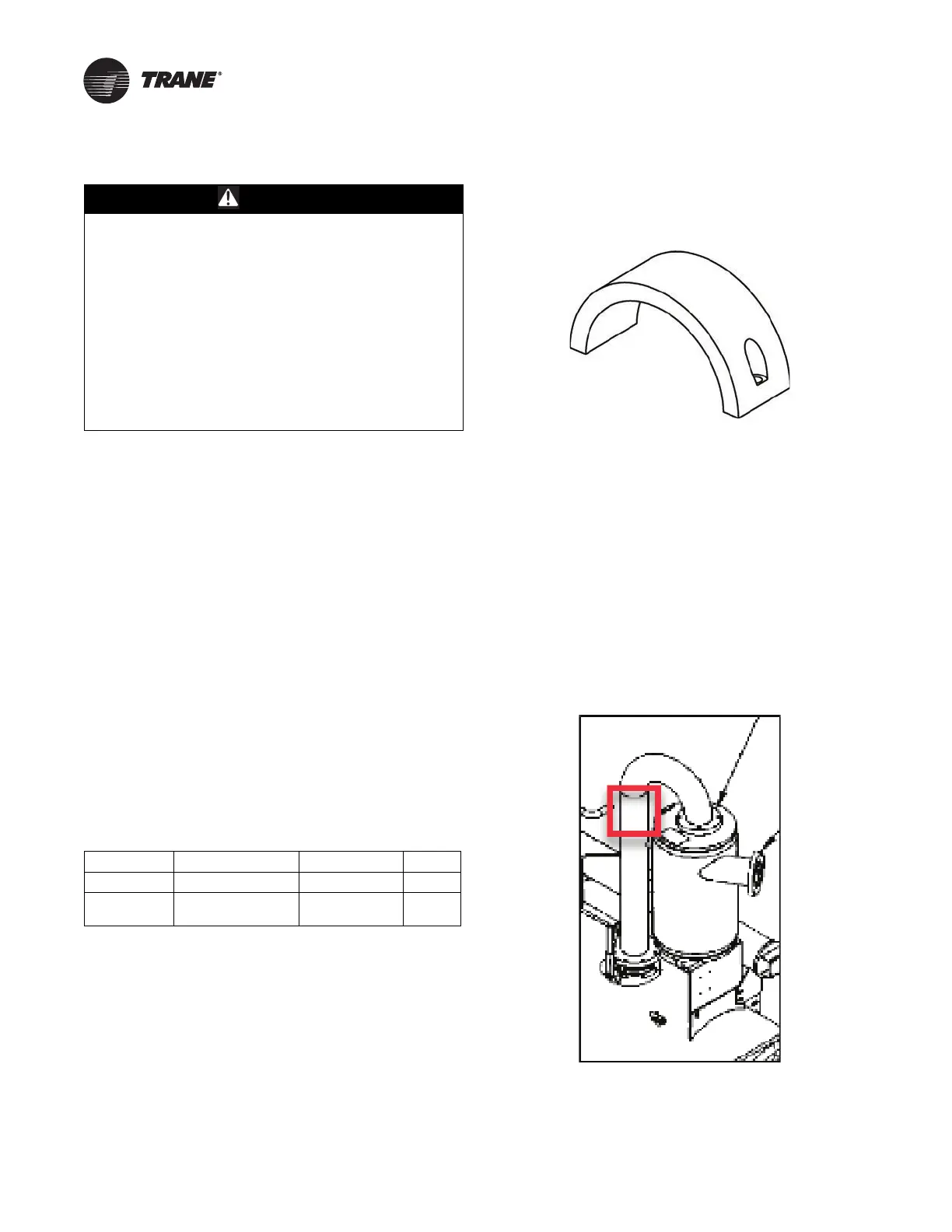
Install 2 weights (4 clamps) on the single oil separator
discharge line as shown in figure below.
• Install on the candy cane line between the oil separator
and the condenser.
• Mount just below the weld or on any smooth surface in that
area.
WARNING
Hazardous Voltage w/Capacitors!
Failure to disconnect power and discharge capacitors
before servicing could result in death or serious injury.
Disconnect all electric power, including remote
disconnects and discharge all motor start/run
capacitors before servicing. Follow proper lockout/
tagout procedures to ensure the power cannot be
inadvertently energized. For variable frequency drives
or other energy storing components provided by Trane
or others, refer to the appropriate manufacturer’s
literature for allowable waiting periods for discharge of
capacitors. Verify with a CAT III or IV voltmeter rated per
NFPA 70E that all capacitors have discharged.
Table 7. Line weight kit 017500010100
Component Mnuemonic Number Decsription Quantity
Clamp CMP01430 Clamp, Line Weight 4
Screw SCR02687
M6 x 30MM, SCH
CAP
4
Figure 27. Individual clamp (two required for each line
weight)
Figure 28. Line weight installation location – B-frame
compressors
 Loading...


