Installation
SO-SVN048A-EN 35
Solid State Starter Panel
1. Remove and discard high-fault bracing.
2. Remove and discard power wire from breaker/terminal,
contactors, and motor terminals. See Figure 33, p. 34 for
use of backup wrench.
Note: Be sure to save motor terminal nuts for installation.
3. Remove and discard 1F1/2/3 line side harness.
4. Remove relay 1K11.
5. Remove and discard current transformers: 1T2-1, 1T2-2,
and 1T-31.
6. Remove and discard (if applicable) under/over voltage
transformers: T3-1, 1T3-2, and 1T3-1.
7. Remove and discard terminals 1x3.
8. Remove and save Fuse 1F1/2/3 for later use.
Note: This fuse will be rated at 5 amps (380 to 415 volts)
and 4 amps (460 volts).
9. Remove starter module 1A3.
Note: The liquid level red power wire (64A) is connected
to J3 Pin 1 of the starter module. This will be
connected to the power supply 1A2. Refer to
“Panel Control Wiring,” p. 47.
10. Remove solid state starter module. See Figure 34, p. 34.
Panel Preparation – Close Mount
(Kit 1 – 2 conduit)
If using a remote mount or wall mount option with field-
provided power wire and conduit, skip to “Panel Component
Installation (All Kits),” p. 37.
Refer to Figure 36 during the following procedure.
1. Drill two 2.5-inch diameter holes at Location 2 and
Location 4, as shown in Figure 36. These holes will be
used to route the power wire which connects the unit to the
AFD.
Notes:
• Test-fit the 2.5-inch conduit fittings at the locations to
ensure the conduit and or fitting will not interfere with the
unit evaporator and or panel before drilling holes.
• Depending on the unit’s evaporator size the holes may be
located further inward than specified without interference
between conduit and evaporator. Locating the holes
further inward will aid in harness installation later. Before
drilling, make sure conduit and fittings will not interfere with
evaporator or panel door.
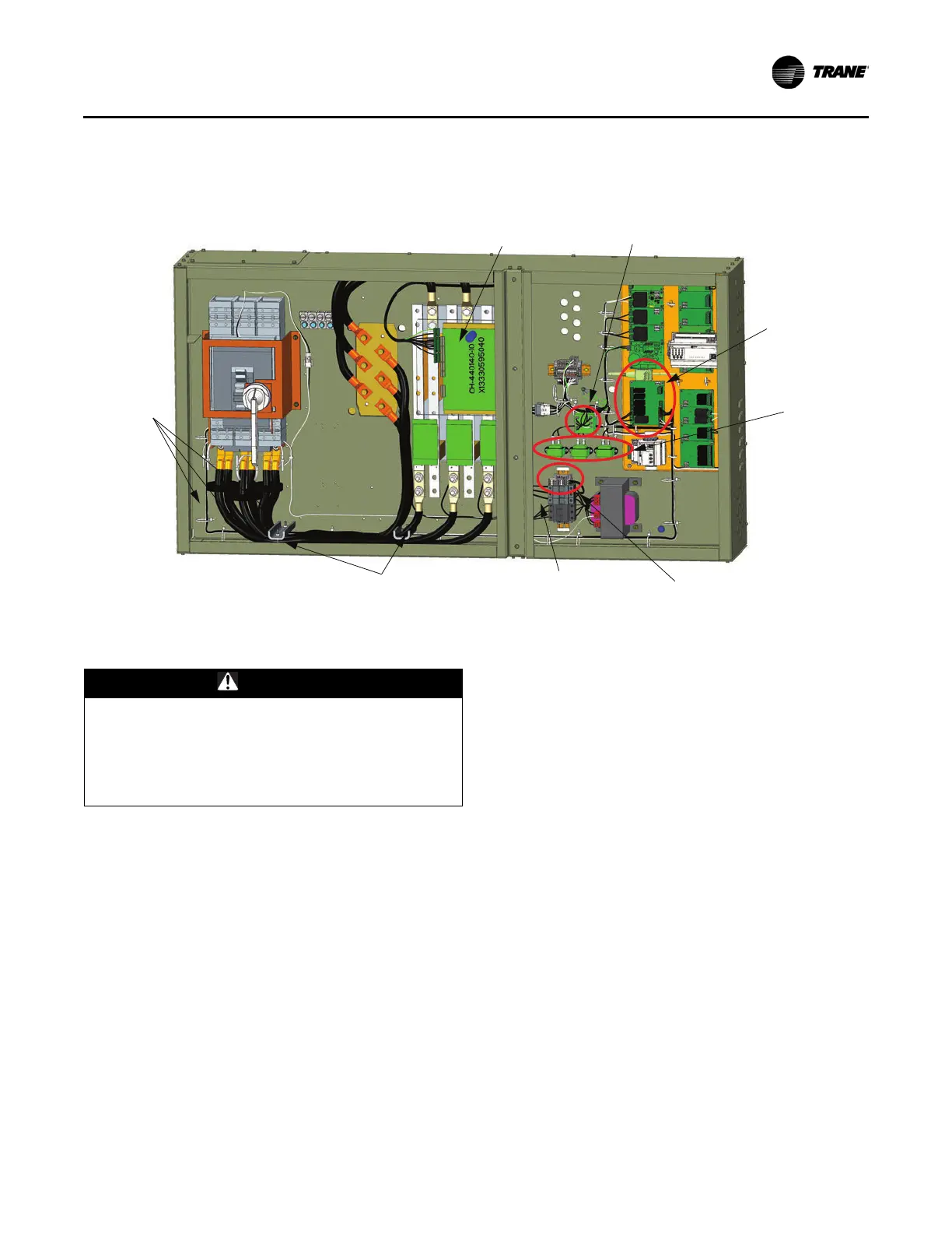
Figure 35. Solid state starter component locations
Solid State
Starter
1A3
1T3-1
1T3-2
1T3-3
1F1/2/3 Fuse
Line-Side
Harness 1F1/2/3
High Fault
Bracing
1T2-1
1T2-2
1T2-3
1K11
WARNING
Connection Leaks!
Failure to follow instructions below could result in
damage to the coil header and cause connection leaks.
Use a backup wrench when attaching piping to coils
with copper headers. Do not use brass connectors
because they distort easily.
 Loading...


