Installation
32 SO-SVN048A-EN
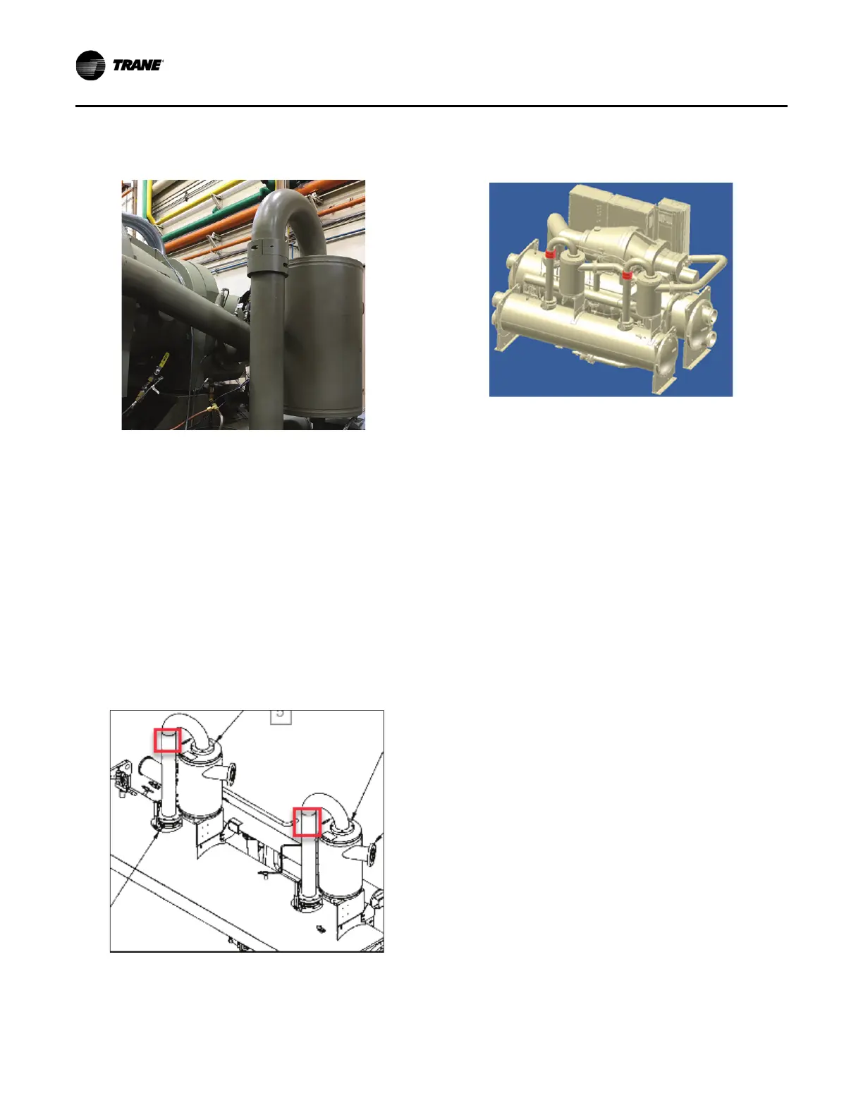
Chillers with C, D, or E-Frame Compressor
Size
• Number of oil separator discharge lines: 2
• Number of kits required: 2
Install 2 weights (4 clamps) on EACH of the two oil separator
discharge lines as shown in figure below.
• Install on the candy cane line between the oil separator
and the condenser.
• Mount just below the weld or on any smooth surface in that
area.
RTHD Tracer
®
AdaptiView™
UC800 Controls Upgrade
If there is an existing CH530 controller, the Tracer
AdaptiView RTHD rotary chiller display upgrade kit
(RCDA) must be installed. Refer to RCDA - Tracer
AdaptiView™ Display Upgrade Kit RTHD Rotary Chiller
Installation Instructions (SO-SVN030*-EN) before installing
the AFDR drive.
If the RTHD to be retrofitted to AFD already has a UC800
Tracer AdaptiView controller, that can be reused.
Important: Regardless if it is new or existing, the UC800
must have a software upgrade to support the
AFDR. For more information, refer to “UC800
Software Installation and Configuration,” p. 50.
AFDR Kit Identification
• Close Mount Kit 1 has two power wire harnesses
• Close Mount Kit 2 has four power wire harnesses
• Remote Mount Kit 3 has NO power wire harnesses or
Modbus
®
cables
Note: The Modbus wiring for the remote mount option
must be purchased separately; refer to “Required
Parts – NOT Supplied,” p. 24 for part numbers to
determine the lengths needed. Purchase
appropriate lengths for the distance required to
wire to the AFD.
Figure 29. Line weight installation location – B-frame
compressors
Figure 30. Line weight installation location – C, D, or
E-frame compressors
Figure 31. Line weight installed on C, D, or
E-frame compressors
 Loading...


