BAS-SVP042A-EN
19
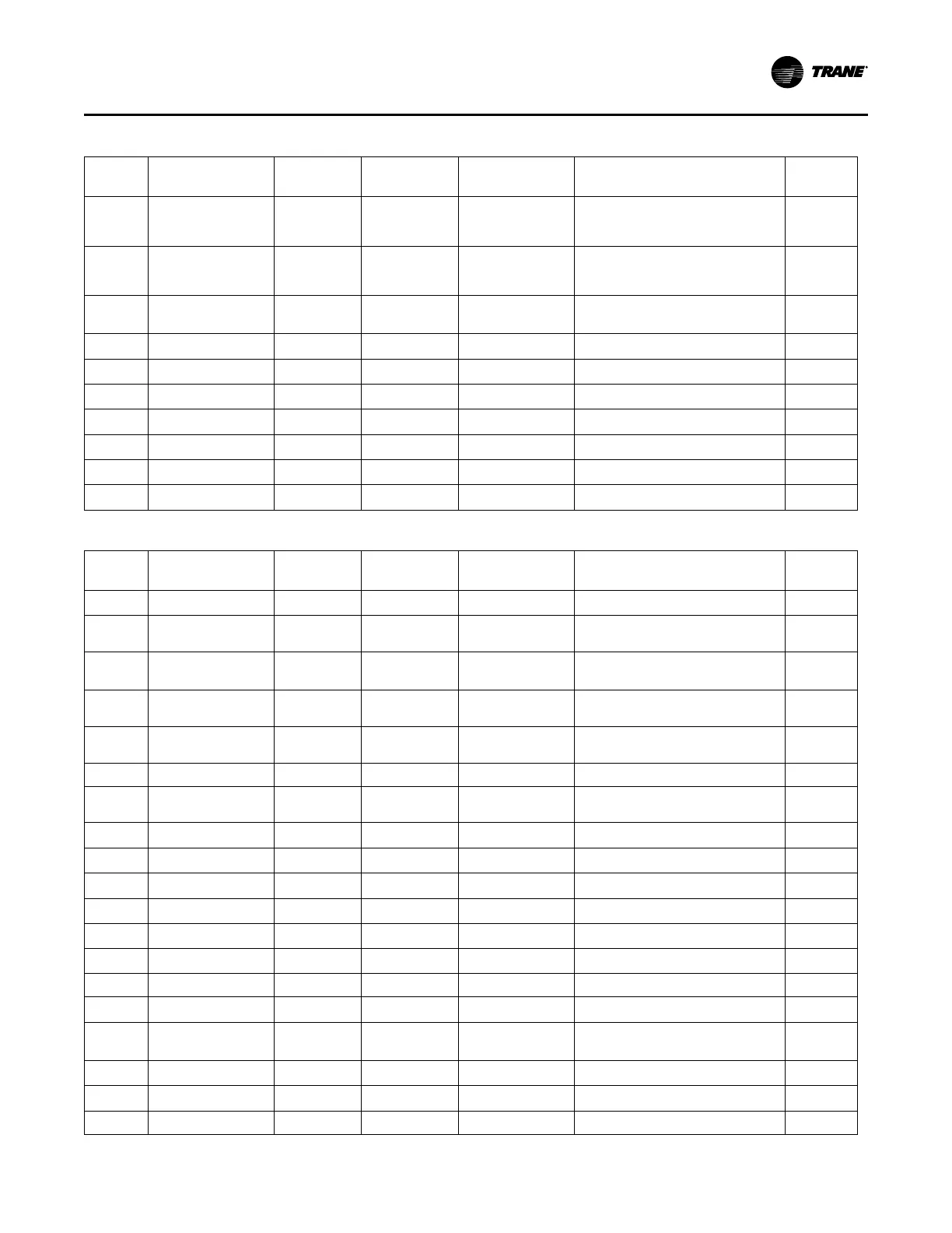
Table 3. Analog Outputs (continued)
Object
Identifi-
er
Object Name
Units of
Measure
Minimum
Maximum
When the Object
Exists
Description
Read/
Write
AO83
Compressor 3
Condenser Regulating
Valve
Percent
0% to 100%
Open
Unit that Circuit 3
has a Water
Regulating Valve
installed
Analog Control that regulates water
throught the water cooled condenser
of the compressor
Read Only
AO84
Compressor 4
Condenser Regulating
Valve
Percent
0% to 100%
Open
Unit that Circuit 4
has a Water
Regulating Valve
installed
Analog Control that regulates water
throught the water cooled condenser
of the compressor
Read Only
AO90
Compressor 1 Variable
Speed Command
Percent
0% to 100%
Speed
Unit where
compressor 1 is a
VFD Compressor
Analog signal that controls the
compressor speed
Read Only
AO96
Supply Fan 1 Speed
Command
Percent
0% to 100%
Speed
Units with at least 1
Fan
Analog signal that Controls the Fan
Speed
Read Only
AO97
Supply Fan 2 Speed
Command
Percent
0% to 100%
Speed
Units with at least 2
Fan
Analog signal that Controls the Fan
Speed
Read Only
AO98
Supply Fan 3 Speed
Command
Percent
0% to 100%
Speed
Units with at least 3
Fan
Analog signal that Controls the Fan
Speed
Read Only
AO99
Supply Fan 4 Speed
Command
Percent
0% to 100%
Speed
Units with at least 4
Fan
Analog signal that Controls the Fan
Speed
Read Only
AO100
Supply Fan 5 Speed
Command
Percent
0% to 100%
Speed
Units with at least 5
Fan
Analog signal that Controls the Fan
Speed
Read Only
AO101
Supply Fan 6 Speed
Command
Percent
0% to 100%
Speed
Units with at least 6
Fan
Analog signal that Controls the Fan
Speed
Read Only
AO105
Water Side
Economizer Valve
Percent
0% to 100%
Open
Units with a Water
Side Economizer
Analog Control that regulates water
throught the water side economizer
Read Only
Table 4. Analog Values
Object
Identifi-
er
Object Name
Units of
Measure
Minimum
Maximum
When the Object
Exists
Description
Read/
Write
AV18
Discharge Air Cooling
Setpoint Max BAS
Temperature
(°C or °F)
10°C (50°F) to
29.4°C (85°F)
Units with Discharge
Air Reset Method.
Sets the maximum Reset Temperature
when in the cooling mode.
Writeable
AV21
Discharge Air
Temperature Setpoint
Active
Temperature
(°C or °F)
-50°C (-58°F) to
236°C (482°F)
All Units
Setpoint the unit is using to control the
discharge air temperature to.
Read Only
AV21
Discharge Air
Temperature Setpoint
Pgain
None
Units with Discharge
Air Reset Method.
P Gain for the PID Discharge Air Reset
Calculation
Read Only
AV24
Discharge Air Cooling
Setpoint BAS
Temperature
(°C or °F)
-50°C (-58°F) to
236°C (482°F)
All Units
User Entered Setpoint to control the
Discharge Air to when in the cooling
mode.
Writeable
AV25
Discharge Air Heating
Setpoint BAS
Temperature
(°C or °F)
-50°C (-58°F) to
236°C (482°F)
Unit with a Heating
Coil
User Entered Setpoint to control the
Discharge Air to when in the Heating
mode.
Writeable
AV52
Cooling Capacity
Status
Percent -150% to 150% All Units
Cooling Capacity actually running on
the unit
Read Only
AV72
Discharge Air
Temperature Setpoint
Local
Temperature
(°C or °F)
-50°C (-58°F) to
236°C (482°F)
Units with Discharge
Air Reset Method.
Setpoint the unit is using to control the
discharge air temperature to.
Read Only
AV72
Duct Static Pressure
Active
Pressure
in(H2O)
-5.0 to 5.0 in
(H2O)
All Units
Duct static pressure the unit is
controling the fans to.
Read Only
AV73
Space Temperature
BAS
Temperature
(°C or °F)
-50°C (-58°F) to
236°C (482°F)
Units with Discharge
Air Reset Method.
Setpoint the unit is using to control the
discharge air temperature to.
Writeable
AV74
Space Temperature
Active
Temperature
(°C or °F)
-50°C (-58°F) to
236°C (482°F)
Units with Discharge
Air Reset Method.
Setpoint the unit is using to control the
discharge air temperature to.
Read Only
AV91
Duct Static Pressure
Setpoint BAS
Pressure
in(H2O)
-0.0 to 5.0 in
(H2O)
All Units
User entered Setpoint to control the
fans to the desired pressure.
Writeable
AV92
Duct Static Pressure
Setpoint Active
Pressure
in(H2O)
-5.0 to 5.0 in
(H2O)
All Units
Setpoint being used to control the fans Read Only
AV101
Supply Fan Speed
Pgain
None 1 to 25 All Units
P Gain for the PID Supply Fan Speed
Calculation
Read Only
AV115
Supply Fan Speed
Status
Percent -150 % to 150 % All Units
Speed the Fans are actually running Read Only
AV124
Cooling Capacity
Request
Percent -150% to 150% All Units
Cooling Capacity needed to meet the
cooling demand.
Read Only
AV129
Dirty Air Filter DP
Setpoint
Pressure
in(H2O)
-10.0 to 5.0 in
(H2O)
All Units
Filter pressure which will generate a
dirty filter alarm when the filter
differential pressure exceeds it.
Writeable
AV133
Active CoolCoil Control
Sensor
Temperature
(°C or °F)
-50°C (-58°F) to
236°C (482°F)
All Units
Active Temperature used for
controlling the cooling calculation
Read Only
AV134
Active CoolCoil Control
Setpoint
Temperature
(°C or °F)
-50°C (-58°F) to
236°C (482°F)
All Units
Active Setpoint used for controlling
the cooling calculation
Read Only
AV139
Cooling PID Output
Percent -150% to 150% All Units
Output from the cooling PID
calculation.
Read Only
OObbjjeecctt aanndd DDiiaaggnnoossttiicc DDaattaa PPooiinnttss
 Loading...


