BAS-SVP042A-EN
9
Checkout
Procedure Measurement
Expected Value
Step 1 Measure AC voltage across the voltage input.
VAC ≈ 0.0 V
AC voltage will affect further
measurement.
Step 2 Measure DC voltage across the voltage termination.
Compare the measured voltage with
the expected value based on the
manufacturer’s specification and
current conditions.
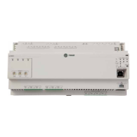
Current Inputs
The sensor sources 4–20 mA and is powered.
Checkout
Procedure Measurement
Expected Value
Step 1 Measure AC voltage across the current input.
Vac ≈ 0.0 V
AC voltage will affect further
measurement.
Step 2 Measure the DC current across the current input.
Compare the measured current with
the expected value based on the
manufacturer’s specification and
current conditions.
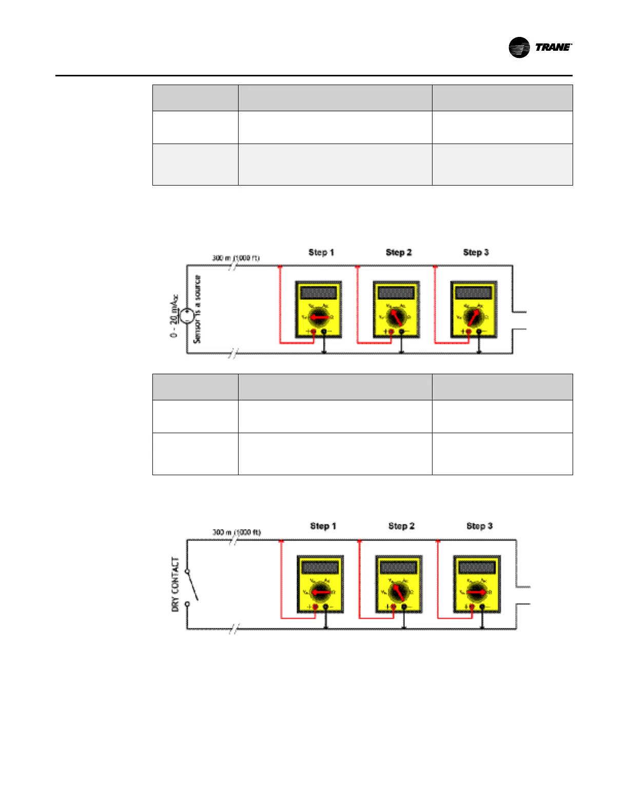
Binary Inputs
TTrraacceerr UUCC660000 PPrree--ppoowweerr CChheecckkss
 Loading...


