8
BAS-SVP042A-EN
Tracer UC600 Pre-power Checks
To avoid equipment damage, a pre-power check for inputs and outputs is recommended before
applying power to the Tracer UC600. Before applying power, check for the following:
• All thermistors; check for resistance by using a digital multimeter (DMM). At room
temperature, the resistance reading will be approximately 11 kΩ for a Trane thermistor.
• Thumbwheels; range between 189 Ω and 890 Ω.
• Binary outputs; check for any shorts.
• Analog outputs; verify that AC voltage is not present and that the load does not have 24 Vac
or 120 Vac.
This section provides illustrations and methods of how to check the Tracer UC600 points before
connection has been made and power applied. The step numbers in each illustration correspond
to the information in each table.
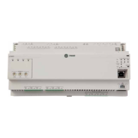
Resistive Inputs
Checkout
Procedure Measurement
Expected Value
Step 1
Measure AC voltage across the resistive
termination.
Vac » 0.0 V AC voltage will affect further
measurement.
Step 2
Measure DC voltage across the resistive
termination.
Vdc » 0.0 V DC voltage will affect further
measurement.
Step 3
Measure the resistance across the resistive
termination.
Compare the measured resistance with the
expected value based on the manufacturer’s
specification and current conditions.
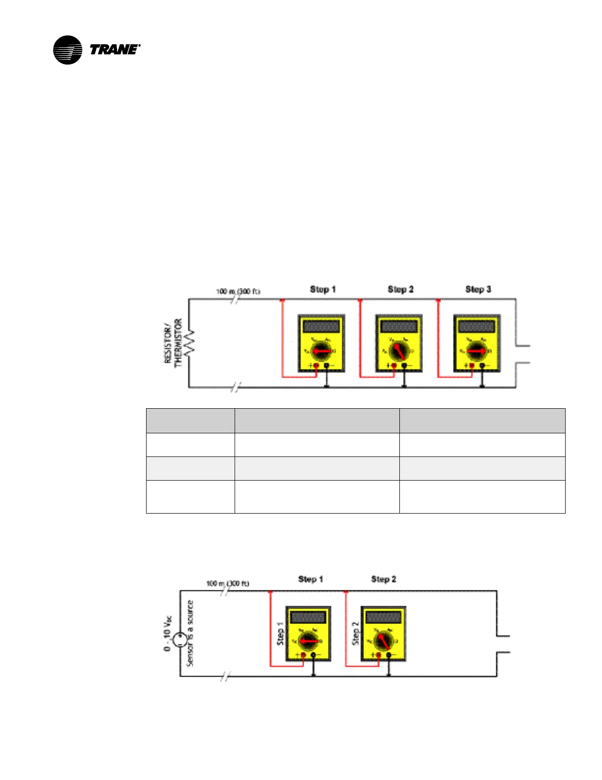
Voltage Inputs
The sensor senses the voltage and is powered.
 Loading...


