6
BAS-SVP042A-EN
UC600 Rotary Swtiches and LEDs
Setting Addresses Using Rotary Switches
There are three rotary switches on the front of the Tracer UC600 for the purpose of defining a
three-digit address when it is installed on a BACnet communications network. The three-digit
address setting is used as both the rotary switch value and the BACnet device ID.
For Trane BACnet MS/TP systems, the rotary switch value must be between 1 and 127. Although
“0,0,0,” is a valid BACnet address, Trane reserves this address for the Tracer SC controller. For
non-Trane systems, see . All device addresses on the BACnet MS/TP link must be unique.
• Before powering up Tracer UC600, set the rotary switch value as shown in the following
figure.
• If the Tracer UC600 was previously powered up, do the following if you wish to make
changes:
– Make the preferred changes to the rotary switch value as illustrated in .
– Power down the Tracer UC600; when re-powered the new rotary switch value should be
active.
• For controllers that are connected through BACnet/IP, or wireless via ZigBee™, valid unit
controller rotary switch values can range from 001 to 999.
NNoottee:: Valid rotary switch values used with the Tracer UC600 are 001 to 120 for BACnet MS/TP.
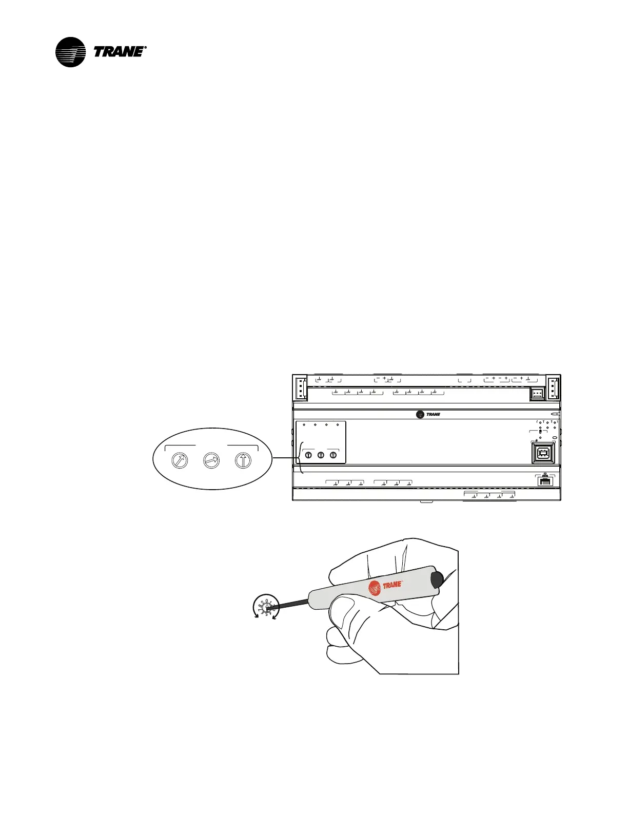
Figure 1. Setting rotary switch values on UC600
A
O
6
UI
14
A
O
5
UI
13
A
O
4
UI
12
A
O
3
UI
11
A
O
2
UI
10
A
O
1
UI
9
B
O
4
B
O
3
B
O
2
B
O
1
RELAYS
0
.
5
A MAX
IM
C
1
IM
C
P
1
UI
8
UI
7
UI
6
UI
5
UI
4
UI
3
UI
2
UI
1
IMC
+
24
VDC
LINKOUT
+
24
VDC
+
24
VDC
OUT
24
VAC
MBUS
OUT
24
VAC
XFMR
24
VAC
SERVICE TOOL
SERVI
C
E
LINK
ACT
IM
C
MBUSLINK
RX
TX
U
C
600
ADDRESS
0
1
2
3
4
5
6
7
8
9
x1
0
1
2
3
4
5
6
7
8
9
x10
0
1
2
3
4
5
6
7
8
9
x100
B
O
4
B
O
3
B
O
2
B
O
1
ADDRESS
0
1
2
3
4
5
6
7
8
9
x1
0
1
2
3
4
5
6
7
8
9
x10
0
1
2
3
4
5
6
7
8
9
x100
Rotary switches after
addresses have been set
IImmppoorrttaanntt:: Each Tracer UC600 device on the BACnet link must have a unique rotary switch value,
otherwise communication problems will occur.
Use a 1/8 in. (3 mm) flathead screwdriver
to set rotary switches. Switches rotate
in either direction.
Location of LEDs
Light emitting diodes (LEDs) indicate the operation and communication status of the controller.
For detailed information about wiring communication links, refer to the BACnet Best Practices
and Troubleshooting Guide (BAS-SVX51).
 Loading...


