CNT-SVX17G-EN 105
Appendix D: Reheat Actuation Schedule Tables
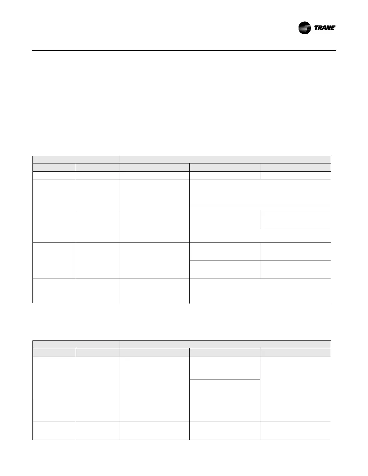
Reheat Actuation Schedule With Parallel Fan Present
Fan powered units only have two outputs available for reheat, the third output is occupied by the
fan output. The series fan runs whenever the airflow is greater than zero. The parallel fan runs
intermittently, as the first stage of reheat. The parallel fan is the first stage of reheat. Its operation
is not limited by the value in communicated auxiliary heat enable. The reheat actuation operation
with parallel fan present is described in the following tables:
• Table 69; Local heat only with parallel fan present
• Table 70; Local and remote heat with local heat pr
iority and par
allel fan present
• Table 71; Local and remote heat with remote heat priority
and parallel fan present
Table 69. Local heat only with parallel fan pre
sent
Configuration Method of control
Local Remote Stage 1
a
Stage 2 Stage 3
Fan Not applicable Parallel Fan Not applicable Not applicable
Fan +
PWM electric
(1 to 2 stages)
Not applicable Parallel Fan
Local PI capacity loop
Each stage represents an equal perc
ent of total capacity (1-stage
= 100%, 2 stages = 50% each)
PWM output
Total capacity is limited by communicated auxiliary heat enable.
Fan +
On/Off electric
(1 to 2 stages)
Not applicable Parallel Fan
Local thermostatic
On: Zt < HSP – 1°F (0.56°C)
Off: Zt HSP – 0.5°F (0.28°C)
Loc
al thermostatic
On: Zt < HSP – 2°F (1.11°C)
Off: Zt HSP – 1.5°F (0.83°C)
Each stage represents an equal percentage of total capacity.
To
tal capacity is limited by communicated auxiliary heat enable.
Fan +
On/Off hot water
(1 to 2 stages)
Not applicable Parallel Fan
Local thermostatic
On: Zt < HSP – 1°F (0.56°C)
Off: Zt HSP – 0.5°F (0.28°C)
Not ap
plicable
Total capacity is limited by
com
municated auxiliary heat
enable.
Not applicable
Fan +
Modulating hot
wat
er
Not applicable Parallel Fan
Local PI capacity loop
Modulating valve capacity = Total capacity
Valve drive incrementally open/closed
Total capacity limited by communicated auxiliary heat enable
a. For more information on fan operation, see “Fan Control,” p. 64.
Abbreviations: Zt = Zone temperature; HSP = Heating setpoint
Table 70. Local and remote heat with local heat priority and parallel fan present
Configuration Method of control
Local Remote Stage 1
a
Stage 2 Stage 3
Fan priority
On/Off electric
(1 stage)
Parallel fan
Remote thermostatic
100% of total capacity
On: Zt < HSP
Off: Zt HSP
+ 0.5°
F
Not applicable
Total capacity is limited by
com
municated auxiliary heat
enable.
Fan priority
On/Off hot water
(1 stage)
Parallel fan
Remote thermostatic
100% of total capacity
On: Zt < HSP
Off: Zt HSP
+ 0.5°
F
Not applicable
Total capacity is limited by
com
municated auxiliary heat
enable.

 Loading...


