CNT-SVX17G-EN 67
Sequence of Operations
The ventilation flow control uses nviVentSetpt if it is valid. If nviVentSetpt is not valid, the
ventilation flow control uses one of the following two airflow setpoints:
•If no reh
eat being used, it uses the configured Ventilation Setup Occupied Setpoint;
•If reh
eat being used, it uses the configured Local Heat Minimum Airflow.
Air Valve Control
Ventilation flow control uses the air valve as a constant volume device. The unit is given
a constant flow setpoint for air valve control (configured ventilation setpoint); the air
valve only repositions itself in response to changes in inlet static pressure. By using
pressure independent control for ventilation purposes, a constant volume of fresh air can
be maintained, regardless of small fluctuations in inlet static pressure. Ventilation flow
control unit uses nviVentSetpt if it is valid. The ventilation flow control uses nviVentSetpt
if it
is valid. If nviVentSetpt is not valid, the ventilation flow control uses one of the
following two airflow setpoints:
•If no reh
eat being used, it uses the configured Ventilation Setup Occupied Setpoint;
•If reh
eat being used, it uses the configured Local Heat Minimum Airflow.
Staged Reheat Control (Electric and Hot Water)
The heat outputs of the controller are binary. Only discrete levels of discharge air
temperature are possible. Since discrete discharge air temperature levels do not always
provide an instantaneous temperature within the required band, staged reheat controls
to a 30-minute average discharge air temperature. The discharge air temperature
setpoint is limited from 20°F to 70°F.
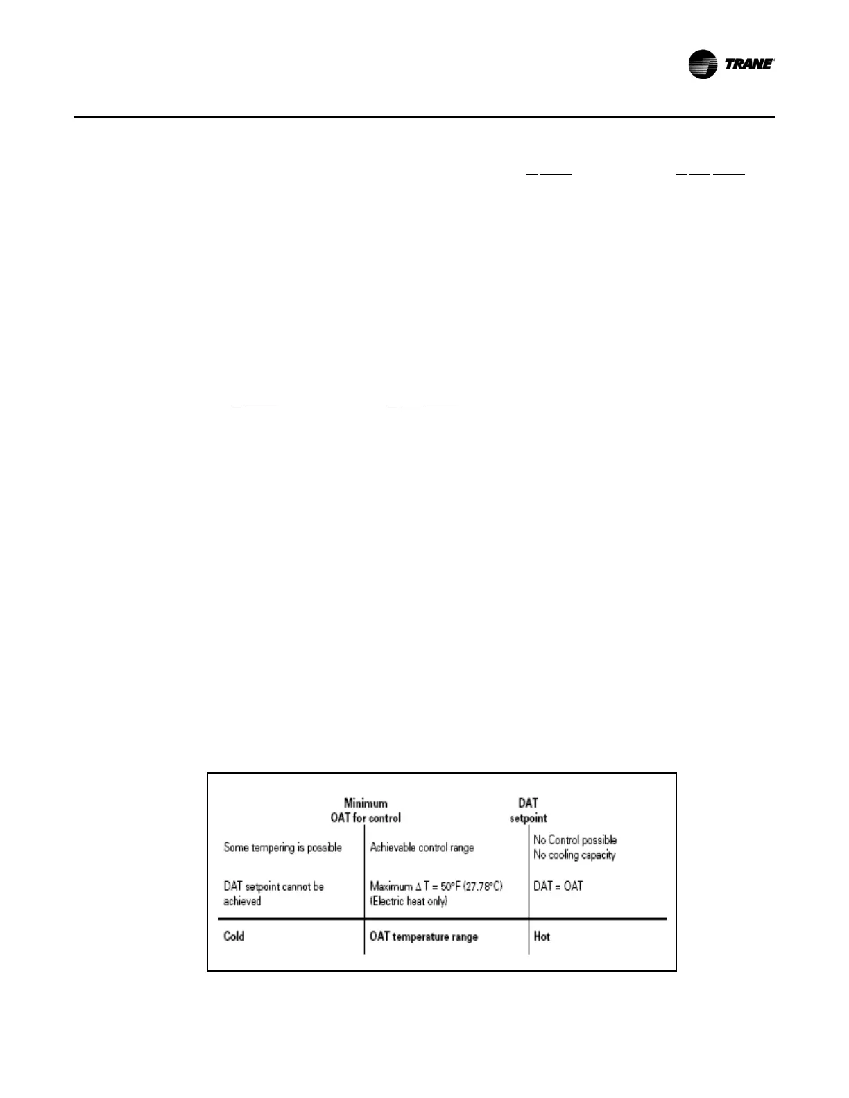
Staged Electric Reheat Control
Units that are equipped with electric reheat should be sized so that the maximum
temperature rise across the heating elements is 40°F to 48°F (22.22°C to 26.67°C); it
should never exceed 50°F (27.78°C) for safety reasons. These values were selected to
allow the largest control range without damage to the heater elements. Figure 4 shows
th
e achievable control range for ventilation flow control staged electric heat.
Figure 4. Ventilation flow control staged electric heat achievable control range

 Loading...


