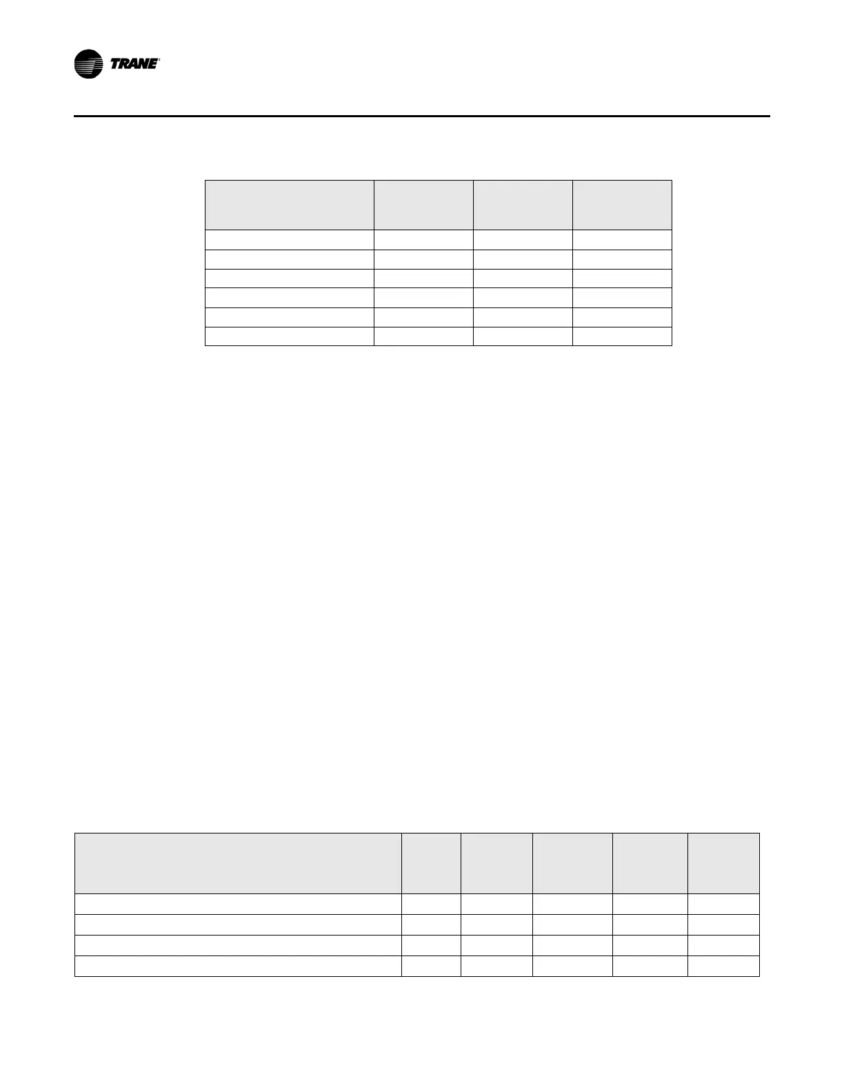
Table 18.Flow tracking emergency override operation
Communicated
emergency override
No heartbeat Fan
Reheat
output
Air valve
Normal or not valid
a
Don’t care Don’t care Normal
Pressurize Don’t care Don’t care Closed
Depressurize Don’t care Don’t care Open
a
Purge Don’t care Don’t care Open
a
Shutdown Don’t care Don’t care Closed
Fire Don’t care Don’t care Closed
28 CNT-SVX17G-EN
Sequence of Operations
Manual Output Test
The manual output test sequence verifies output and end device operation and can be
conducted to verify output wiring and actuator operation without using the Rover
®
service tool. It can also be used during air balancing or water balancing.
Many service calls are initiated due to unit diagnostics. This manual output test sequence
(see
Ta
ble 19) attempts to clear unit diagnostics and restore normal unit operation prior
to t
esting the outputs.
If the diagnostics remain after an attempt to clear them, the status LED flashes in a tw
o-
blin
k pattern. The two-blink pattern indicates that the diagnostic condition is still present
and may affect or disallow the manual output test. For information on which diagnostics
cause a two-blink pattern, refer to Table 48 on page 80 and Table 55 on page 83.
The manual output test terminates when it has advanced completely through the test
seque
nce or w
hen the controller times out as a result of remaining in a single step for one
hour. The outputs are not subject to minimum times during the test sequence. However,
the test sequence only permits one step per second, which enforces a minimum output
time.
All diagnostics other than the following are ignored during manual test:
• Ventilation flow control, freeze protection (low discharge air temperature);
• Low airflow diagnostic will prevent local electric reheat.
a. Open to configured maximum airflow setpoint.
Table 19.Manual output test sequence
Step
a
Air
valve
close
Air valve
open
Heat 1 or
water
valve
close
Heat 2 or
water
valve
open
Heat 3 or
fan On/
Off
1. Off
b
Off Off Off Off Off/Off
2. Air valve opens
c
Off On Off Off Off/Off
3. Air valve stops opening; fan turns On
Off Off Off Off Off/On
4. Heat 1 turns On/water valve closes
Off Off On Off Off/On

 Loading...


