66 CNT-SVX17G-EN
Sequence of Operations
Ventilation Flow Control Mode
Ventilation flow control (VFC) is one of three supported control algorithms. It is applied
to a VAV terminal and used to temper cold outdoor air (OA) that is brought into a building
for ventilation purposes. The tempered air is intended to supply an air-handling unit
(AHU), which provides comfort control to the zones it is serving. The VAV terminal
supplies the correct amount of ventilation air and, when possible, tempers the ventilation
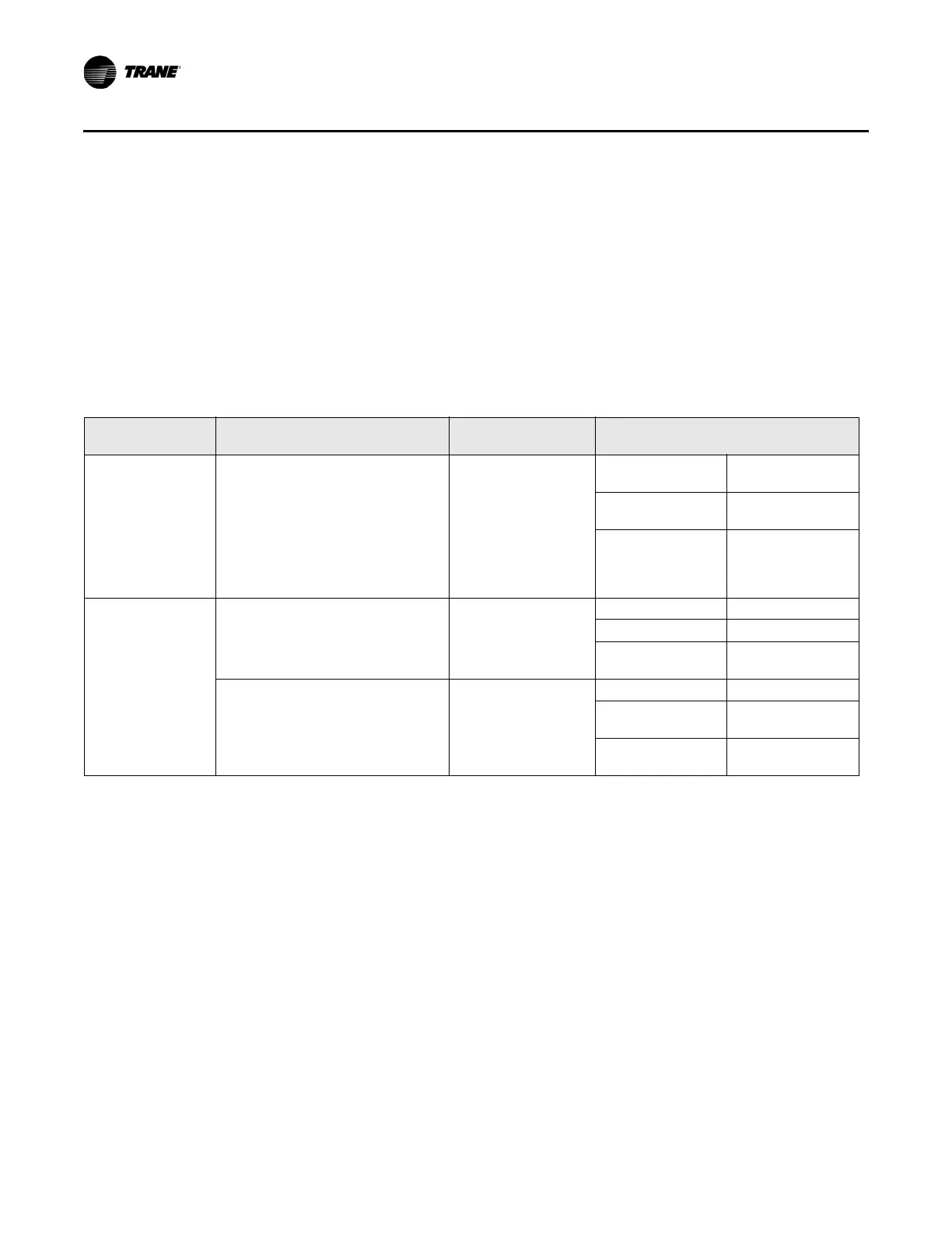
air to reduce the load on the air handler. Table 42 provides the ventilation flow control
out
put
s. For more information on ventilation flow control operation, refer to Table 63 on
page 95.
Table 42.Ventilation flow control outputs
Occupancy
mode
Source temperature Air valve control Reheat control
Occupy standby
bypa
ss
Any Constant volume (if
valid,
communicated
ventilation setpoint;
if not valid,
configured
ventilation setpoint)
Electric VFC staged reheat
cont
rol
Staged hot water VFC staged reheat
control
Modulat
ing hot
wat
er
VFC modulating
reheat control
(same as STC
capacity control)
Unoccupied Communicated source
te
mperature (if valid; if not valid,
discharge air temperature) greater
than configured OA low limit
Closed, 0% Electric Off
Staged hot water Off
Modulating hot
wa
t
er
Off
Communicated source
te
mperature (if valid; if not valid,
discharge air temperature) less
than configured OA low limit
Closed, 0% Electric Off
Staged hot water On, 100% freeze
pr
otectio
n
Modulating hot
wa
t
er
On, 100% freeze
protection
The ventilation flow control process is a constant volume, variable temperature process.
Single duct VAV units with either electric or hot water reheat are used. Fan-powered units
are not used for ventilation flow control.
Ventilation flow control must have an auxiliar
y te
mperature sensor that is located and
configured as a discharge air temperature (DAT) sensor. The required range of discharge
air temperature setpoints is 45°F to 70°F (7.22°C to 21.11°C).
Ventilation flow control staged reheat control (
e
lectric or hot water) achieves a 30-minute
average discharge air temperature to within ±5°F (±2.78°C) of the discharge air
temperature setpoint when the inlet temperature is within the control range.
Ventilation flow control modulating reheat cont
rol (
hot water only) achieves a discharge
air temperature to within ±5°F (±2.78°C) of the discharge air temperature setpoint when
the inlet temperature is within the control range.

 Loading...


