CNT-SVX17G-EN 29
Sequence of Operations
To perform manual output testing:
1. Press and hold the TEST push button for at least three seconds. The green status LED
turns Off, confirming the Test button was pressed.
2. Release the Test but
ton to start the manual output test. The manual output test is in
step one. The green status LED is blinking in one of two patterns. If the green status
LED blinks once, no diagnostics are present. If the green status LED blinks twice,
diagnostics are present.
3. Press the TE
ST button (no more than once per second) to advance through the test
sequence. Test steps are not skipped. For example, if the unit does not have Heat 3,
advancing to step 6 has no effect, but you still must advance to step 6 before
advancing to step 7.
Alternatively, the service override mode enables the Rover
™ service tool to override all
outputs over the communications network. This mode is useful for water balancing, air
balancing, test, and commissioning. The implementation mimics the manual output test.
The mode field of reported unit status a
nd reported heat/cool mode reports TEST during
the manual output test.
A manual override timer is used to limit the leng
th of the override request. This timer is
set to 60 minutes at the start of the manual output test, and reset to 60 minutes each time
the manual output test is advanced to the next step either by pressing the Manual Test
button or on receipt of a communicated value.
Auto-commissioning Test Sequence
The controller auto-commissioning test sequence (see Table 20 below) validates both
the proper operation of all outputs and the capability to measure all inputs. The purpose
of the test sequence is to minimize the labor required to commission the unit in the field.
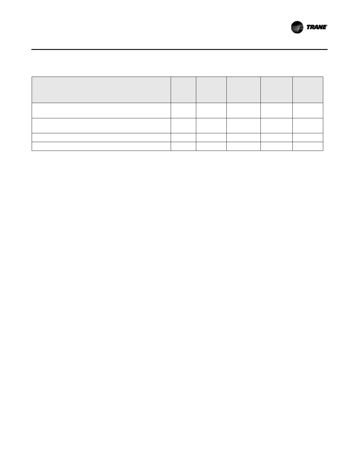
5. Heat 1 turns Off; Heat 2 turns On/water valve
opens
Off Off Off On Off/On
6. Heat 2 turns Off; Heat 3 turns On/water valve
closes
Off Off Off/On Off On/On
7. Heat 3 turns Off; air valve 1 closes; fan turns Off
On Off Off Off Off/Off
d
8. Exit
e
a. The invalid unit configuration diagnostic causes the controller to exit manual output test.
b. On activating the manual output test function, all outputs are turned Off or closed. The green status LED blinks in a one-blink
pattern during the manual output test if no diagnostics are present. The green status LED blinks in a two-blink pattern during
the manual output test if a diagnostic is present.
c. At the beginning of step 2, the controller attempts to reset all diagnostics. The low airflow diagnostic prevents local electric
reheat from energizing. A ventilation flow controller with a freeze protection active diagnostic will not run the manual output
test.
d. A series fan stays On until the air valve is closed.
e. After the last step, the test sequence performs an exit. This initiates a reset and attempts to return the controller to normal
operation.
Table 19.Manual output test sequence (continued)
Step
a
Air
valve
close
Air valve
open
Heat 1 or
water
valve
close
Heat 2 or
water
valve
open
Heat 3 or
fan On/
Off

 Loading...


