2-26 AeroTrak
®
Handheld and Remote Airborne Particle Counters
Det e c t or Bo a r d Rep l a c ement
1. Follow the instructions in the disassembly section and remove the
optics block from the Model 9303.
2. Unplug cables from detector board.
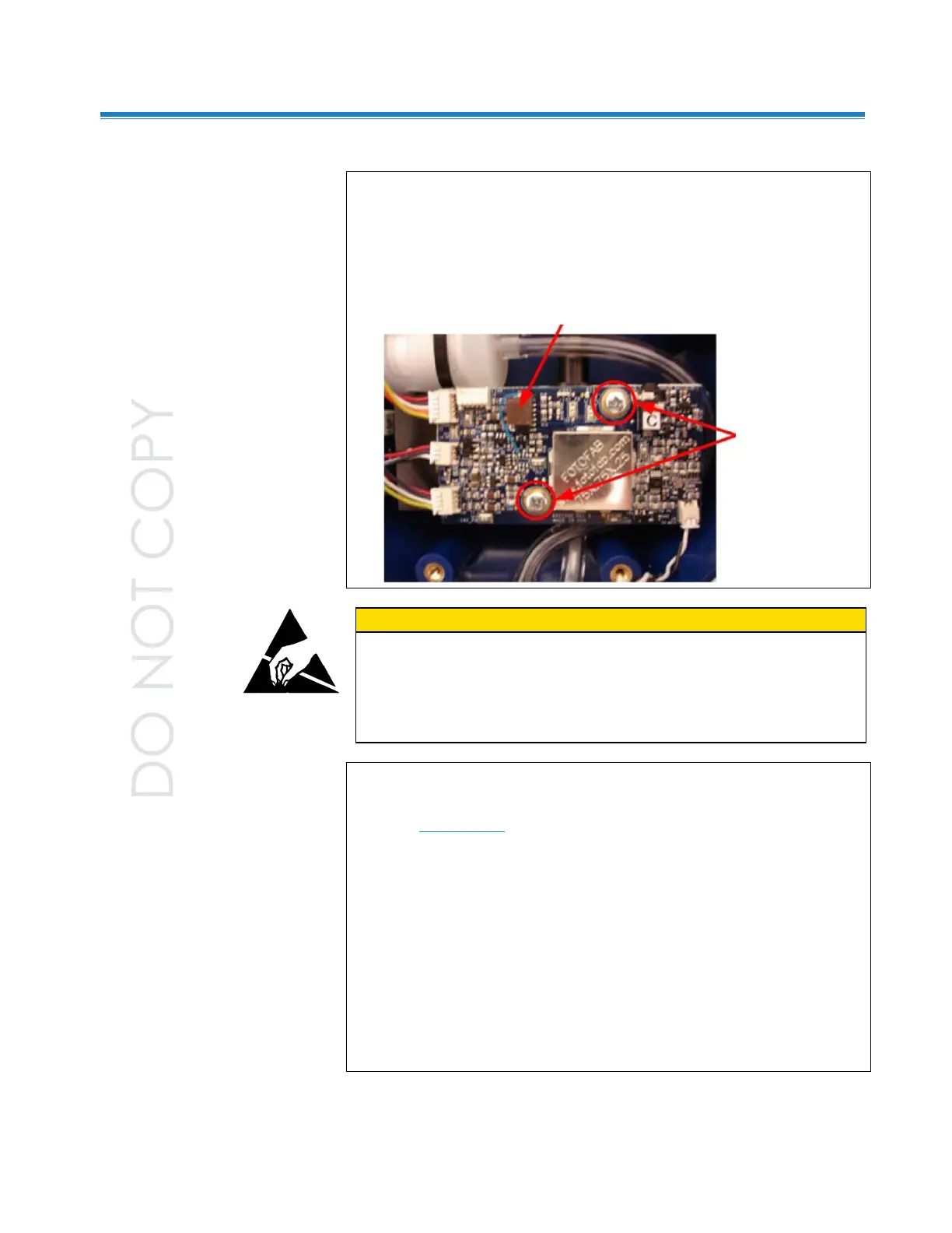
3. Remove the two Phillips head screws fastening the detector board to
the optics block.
C A U T I O N
The electronic circuits within this instrument are susceptible to
electro-static discharge (ESD) damage. Use ESD precautions to
avoid damage.
• Use only a table top with a grounded conducting surface.
• Wear a grounded, static-discharging wrist strap.
4. Pull the detector board straight out of the optics block.
5. Remove the new detector board from service kit 9303 Detector
PCB (S7000005). Install and fasten in place with the two Phillips
head screws.
6. Turn the laser current adjustment pot fully counter-clockwise.
7. Remove beam block and place a laser power meter in front of the
opening in the optics block.
8. Reconnect all cables to main board and power up the unit. Adjust the
potentiometer until the power meter reads 40 mW ±0.5 mW [Melles
Griot power meter] or 38 mW ±0.5 mW [Newport power meter] at the
beam dump.
9. Turn power off and re-install beam block.
10. Re-assemble unit and calibrate.
Laser current adjustment pot
Remove screws
 Loading...