General Maintenance–Model 7301-P 4-19
Rep l a c ing t h e Laser A s sembly
The laser assembly should be replaced to correct the laser current
status error. The steps below show how to replace the laser assembly in
the instrument.
Replacement part needed is replacement laser assembly (S7000009).
C A U T I O N
Laser replacement needs to be done in an ESD controlled environment
with a minimum of one ESD table mat and a wrist strap connected to the
installer.
N O T I C E
Before replacing the laser, check the revision on the detector PCA
(6001939). If the detector PCA is revision E or older, order a
replacement which is revision F or newer.
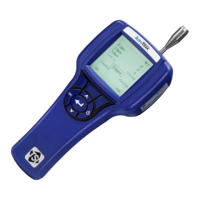
1. Follow the disassembly instructions to remove the optics block from
the chassis.
2. Reconnect the main board to the optics block along with the keypad
to the main board. This will allow you to power up the laser for setup.
DO NOT apply power to the unit at this time.
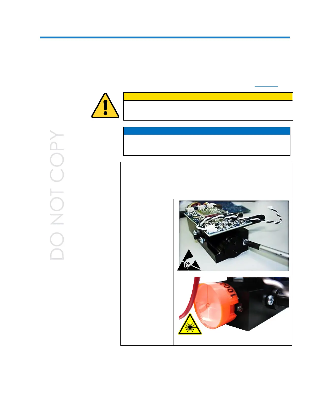
3. Remove the
beam block from
the optics block.
Remove the
Phillips head
screw holding
the beam block
in place and pull
the beam block
straight out of
the optics
assembly.
4. Insert the laser
alignment mask
into the optics
assembly where
the beam block
was removed.
Align the notch
in the mask with
the threaded
mounting hole in
the optics block.
 Loading...