THE MICRO
WAVE SYSTEM
TOP VIEW
SIDE OF OVEN
T2
240V
208V
1
2
3
Brown
Blue
Orange
Brown
Blue
1
2
3
208V
240V
T1
Orange
FT1
240
V
208V
1
2
3
Orange Dot
FT2
240
V
208V
1
2
3
Brown
Blue
Brown
Blue
Orange
Orange
: High Voltage Transformer Wiring
: Filament Transformer Wiring
WAVE GUIDE REPLACEMENT AND CLEANING
: If the Wave Guide is contaminated with
excess debris, it is very important to clean and dry
the Wave Guide. Dirt and contaminates in the Wave
Guide can cause premature Magnetron failures.
1. Remove the Wave Guide Cover. See Wave Guide
Co
v
er R
eplacement on page 24.
2. Remove the two
(2) right and left most #8-32
x 3/8”
screws securing the Wave Guide.
3. The Wave Guide should now be loose so as to
easily slide out from the right side of the oven.
I
f r
eplacing the
W
av
e Guide proceed to Step 6.
If cleaning continue on to Step 4.
:
T
ake care not to damage the insulation
when r
emoving the Wave Guide.
4. Thoroughly clean the contaminated Wave Guide
using any standard degreaser.
5. Thoroughly rinse and dr
y the
Wave Guide
before reinstalling.
6. Reinstall the clean or new Wave Guide using the
four (4) #8-32 x 3/8” mounting screws removed
in Step 2.
7. Reinstall the Wave Guide Cover.
HIGH V
OLTAGE TRANSFORMER AND FILAMENT
TRANSFORMER REPLACEMENT
The proper reinstallation of the High Voltage and
Filament Transformer is critical as both Transformers
ar
e equipped with 208
V
A
C and 240
V
A
C taps.
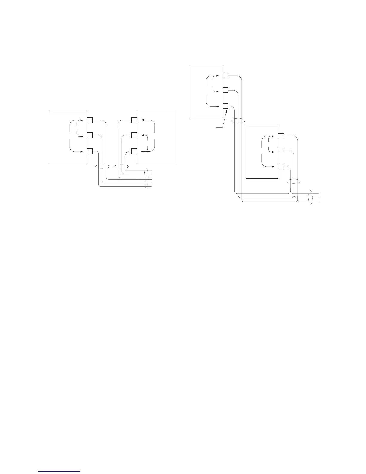
Wiring the High V
olt
age T
r
ansformer
U
pon r
emo
ving a High Voltage Transformer, make
sure to note where each wire was installed. Refer to
the top view diagram detailing the proper wiring
(Figure 18) and the Schematic on the inside of
page 49.
As sho
wn in F
igur
e 18,
T
ransformers ar
e installed
mirror opposite and wired
180
º
out-of-phase. It is
essential for longevity that H
igh
V
oltage Transformers
r
emain 180
º
out-of-phase.
This can be checked by
placing a volt meter across terms
T1-1 and T2-1.
26
 Loading...