41
THE CONVECTION CIRCUIT
The Convection Circuit provides the high temperature
airflow necessary to brown and cook food items.
CONVECTION SYSTEM COMPONENTS
The following is a description of each component
within the Convection Circuit and how each acts
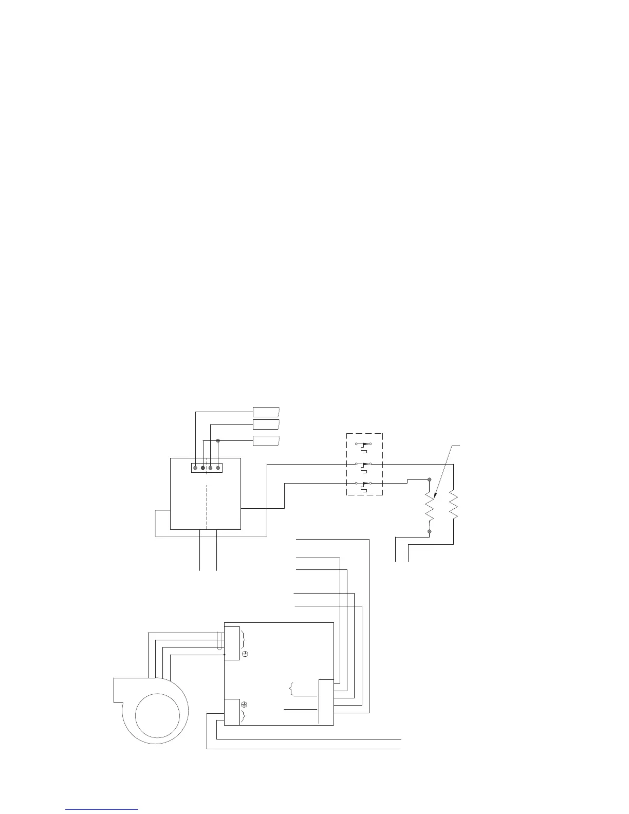
within the Circuit. Figure 31 below shows a block
diagram of the Convection Circuit.
Main Convection Heater (P/N 100661)
The Main Convection Heater is an open coil style
heater rated at 3300 watts at 208 VAC with a
resistance of 13.11 Ohms. The Convection Heater
is controlled by the K4 Solid State Relay (SSR)
(P/N 101284).
Convection Motor (P/N 100882)
The Convection Motor is a Brushless DC Switch
reluctance type. Its top speed is 7200 RPM at 1 HP.
The Motor is controlled by a proprietary controller.
Motor Controller (BMSC) (P/N 100443)
The Motor Controller is proprietary and will only
operate the Convection Motor described above. The
Motor Controller is controlled on command from
the I/O Control Board and a 0-10VDC speed
command fr
om the I/O Control Board.
High Limit Thermostat (P/N 102075)
The H
igh Limit Thermostat is a 250VAC, 3-Pole,
manual reset thermostat with a trip point of 572
º
F.
The Thermostat, which interrupts power to both
the Convection Heater and the IR Element,
should never operate during normal operation.
BMSC
BLWR
MTR
M1 BLK
M2 RED
M3 WHITE
E
1
2
3
4
240 VAC
3 PHASE
OUT
200-240
VAC IN
1
2
3
SPD CMD
1
2
3
4
5
6
0-10V
I/O COM
ENABLE
I/O COM
STATUE OK
I/O COM
L1
L2
L2
L1
OR-9
RD-24
BK-25
WT-31
BK-32
BL500
BL530
BL540
BL510
K5 K4
B1
B2
A1
A2
SSR
HT520
WH-28
WH-30
RD-19
BR600
1
2
HX ELEMENT
3300 WATTS
13.1 OHMS
(100649)
BOTTOM IR
3000 WATTS
14.4 OHMS
(100661)
BOTTOM IR CONTROL
MAIN HX CONTROL
+24
C
NC
32
31
C
NC
22
21
C
NC
12
11
OT1
MANUAL RESET
: Conv
ection Cir
cuit B
lock D
iagram
 Loading...