Tyco Electronics Galaxy SC Controller J85501F-1
Issue 13 February 2001 Product Description 2 - 7
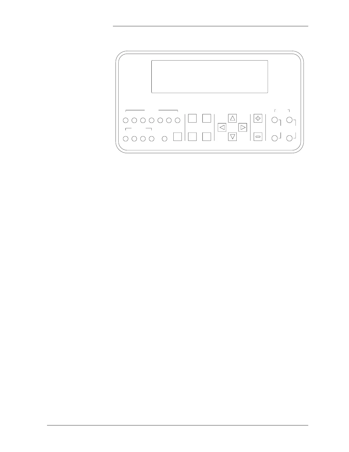
LEDs Two rows of LEDs at the left side of the interface board show the source
and severity of various alarms.
An alarm will light two LEDs: one alarm LED and one status LED.
More than one alarm LED may be on at the same time. The ON status
LED and set of relays will be that of the highest severity active alarm.
The first row of seven LEDs, labeled ALARMS, indicate the source of
the alarm (BD, battery on discharge; BATT, battery; DIST,
distribution; RECT, rectifier; AC, ac power supply; RM, remote
monitoring; and CTLR, controller). The user may reconfigure any of
these to signal other conditions via the intelligent controller.
The second row includes five LEDs. The first four LEDs, labeled
STATUS, indicate the severity of the reported alarms (CRIT, critical;
MAJ, major, MIN, minor, and NORM, normal). Another LED, labeled
COM, will be on when the modem is in use. A pushbutton labeled
LAMP TEST is located next to the COM LED.
Test Jacks Located to the far right of the front panel display are two sets of test
jacks. One pair of test jacks is termed Plant Current and the other pair,
Plant Voltage. Voltages measured at these test jacks are obtained from
the two “Vsense” and two “Shunt” connections made to terminal block
TB1, which is located on the BJF fuse termination board. See Figure
3-1. The voltages sent from TB1 to the front panel test jacks are current
limited and ESD protected. The controller uses these voltages to
determine and display the battery plant bus voltage and load current, as
Figure 2-3: Galaxy SC Controller Front Panel
ALARMS
BD BATT DIST RECT AC RM CTLR
LAMP
TEST
HELP ESCAPE
ENTER
ADJUST
PLANT
CURRENT VOLTAGE
VV
MENU
COMNORMMINMAJCRIT
STATUS
 Loading...

