Tyco Electronics Galaxy SC Controller J85501F-1
Issue 13 February 2001 TL1 (Transaction Language 1) and X.25 Interface Appendix D - 5
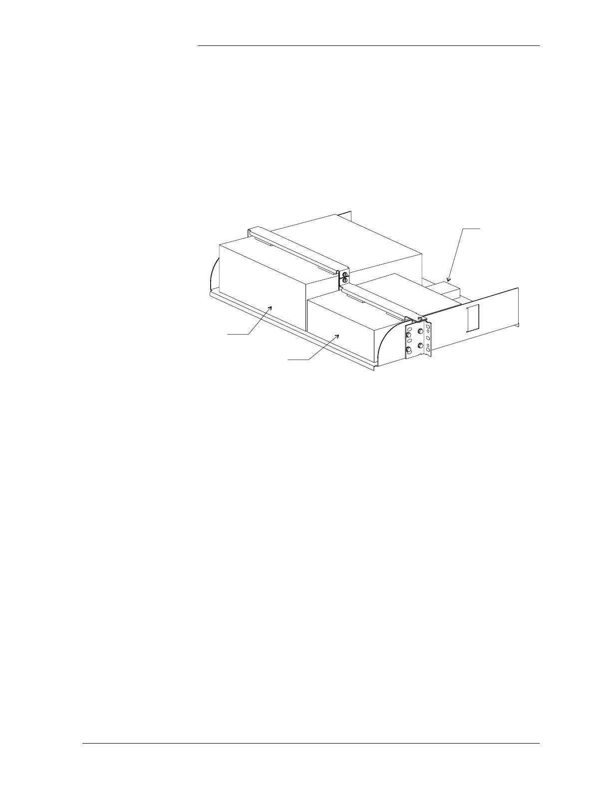
Mount the PAD and DSU units in the shelf:
1. Set the units on the shelf in the positions shown in Figure D-4,
making sure the feet on the bottom of the unit protrude through the
holes in shelf.
2. Set the appropriate bracket across the top of each unit and fasten
using the hardware provided.
Make connections to the system:
1. Connect the Y-cable labeled “To User” to the connector labeled
“STP/X.25” on the back of the PAD unit (see Figure D-1).
2. Connect the “To User” end of the Y-cable to the 3-foot long
DB-25 cable. Connect the other end of the DB-25 cable to the
connector labeled “RS232/530” on the back of the DSU.
3. Connect a terminal to the remaining end of the “To User” Y-cable,
using a standard DB-25 cable. This terminal will be used for setup
of the PAD only.
4. On the RS-232/485 converter, set the DTE/DCE switch to DTE.
5. Set the RS-232/485 converter to 4 wire, transmitter enabled by
RTS communications, by setting the converter's DIP switches to
the positions shown in Table D-2:
Figure D-4: PAD and DSU Mounting Shelf
Optional
RS-232/485
Converter
PAD Unit
DSU
 Loading...

