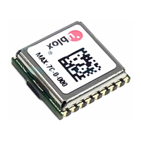
MAX-7 / NEO-7 - Hardware Integration Manual
UBX-13003704 - R09 Production Information Hardware description
Page 10 of 52
USB bus powered / UART Baud Rate 1200
B5 62 06 41 09 00 01 01 30 81 00 00 00 00 F6 F9 1A
USB bus powered / UART Baud Rate 2400
B5 62 06 41 09 00 01 01 30 81 00 00 00 00 F5 F8 19
USB bus powered / UART Baud Rate 4800
B5 62 06 41 09 00 01 01 30 81 00 00 00 00 F4 F7 18
USB bus powered / UART Baud Rate 9600
B5 62 06 41 09 00 01 01 30 81 00 00 00 00 F7 FA 1B
USB bus powered / UART Baud Rate 19200
B5 62 06 41 09 00 01 01 30 81 00 00 00 00 F3 F6 17
USB bus powered / UART Baud Rate 38400
B5 62 06 41 09 00 01 01 30 81 00 00 00 00 F2 F5 16
USB bus powered / UART Baud Rate 57600
B5 62 06 41 09 00 01 01 30 81 00 00 00 00 F1 F4 15
USB bus powered / UART Baud Rate 115200
B5 62 06 41 09 00 01 01 30 81 00 00 00 00 F0 F3 14
To set the default Vendor or Vendor ID, you will need the specific string. To obtain the USB Vendor ID or USB
Vendor string, contact the the nearest Technical Support office by email. You will find the Contact details at
the end of the document.
2.5 Connecting power
u-blox 7 positioning modules have up to five power supply pins: VCC, VCC_IO, V_BCKP, V_ANT and
VDD_USB.
2.5.1 VCC: Main supply voltage
The VCC pin provides the main supply voltage. During operation, the current drawn by the module can vary by
some orders of magnitude, especially if enabling low-power operation modes. For this reason, it is important
that the supply circuitry be able to support the peak power (see datasheet for specification) for a short time.
Some u-blox 7 modules integrate a DC/DC converter. This allows reduced power consumption, especially when
using a main supply voltage above 2.5 V.
When switching from backup mode to normal operation or at start-up, u-blox 7 modules must charge the
internal capacitors in the core domain. In certain situations, this can result in a significant current draw.
For low power applications using Power Save and backup modes it is important that the power supply or
low ESR capacitors at the module input can deliver this current/charge.
Use a proper GND concept. Do not use any resistors or coils in the power line. For ground plane design
see section 3.3.3
2.5.2 VCC_IO: IO supply voltage (MAX-7)
VCC_IO from the host system supplies the digital I/Os. The wide range of VCC_IO allows seamless interfacing to
standard logic voltage levels independent of the VCC voltage level. In many applications, VCC_IO is simply
connected to the main supply voltage.
Without a VCC_IO supply, the system will remain in reset state.
2.5.3 V_BCKP: Backup supply voltage
In case of a power failure on the module supply, the real-time clock (RTC) and battery backed RAM (BBR) are
supplied by V_BCKP. Use of valid time and the GNSS orbit data at start up will improve the GNSS performance
i.e. enables hot starts, warm starts, AssistNow Autonomous and AssistNow Offline. If no backup battery is
connected, the module performs a cold start at power up.
Avoid high resistance on the V_BCKP line: During the switch from main supply to backup supply a short
current adjustment peak can cause high voltage drop on the pin with possible malfunctions.
If no backup supply voltage is available, connect the V_BCKP pin to VCC_IO (or to VCC if not avaiable).

 Loading...